


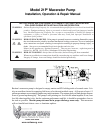

INSTALLATION
Product Specifications
Motor: Seamless can motor, 1/8 hp
Thermally protected
Lead wires: 14 GA
Fuse: See motor label for fuse size
Pump Type: Flexible impeller
Duty Cycle: Intermittent duty only
Ports:
Inlet: 1-1/2” hose barb & 1-1/2” NPT Male
Outlet: 1” hose barb
Impeller: Globe-Blue
Blade: 316 stainless “Double-cut”
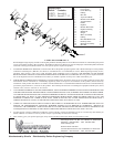
Dimensions: See drawing
Weight: 5 lbs.
Approvals: UL ignition protected, ISO 8846
CSA, CE styles available
Typical Flow: Dependent on fluid viscosity
Chart below based on water
Head Flow gpm[lpm] Max DC Amps
Ft [m] 12 V 24V 12V 24V
0 [0] 13 [49] 13 [49] 17 8
12 Volt System
Min. Wire Size (20 Amps)
Total Wire Length * 3% Drop 10% Drop
feet [m] GA GA
1-10 [.3-3] #10 #16
11-20 [3.3-6] #8 #14
21-30 [6.4-9.1] #6 #12
30-60 [9.1-18.2] #4 #10
*length from power source to motor
and back to ground.
Maximum Operating Head = 30 feet
Electrical Installation Checklist
√ Separate circuit from power source
√ Proper size momentary switch mounted
near pump
√ Proper wire size to length
√ Proper fuse size and type
√ Insulated wire connectors
WARNING:
Pump should be operated on a separate circuit.
Pump should be connected to properly sized
momentary switch. This prevents pump from
damage due to dry run condition.
Switch should be near pump. This will allow
operator to hear change in pump sound when tank
is empty.
NOTE: For proper operation motor must
rotate counterclockwise when viewed from
pump end.
Plumbing Connections
Pump should be mounted as near as possible to tank
to minimize dry run. Pump is self-priming to a
five-foot lift when impeller is wet, four foot lift
when impeller is dry. Pump is more efficient if
mounted near the holding tank.
INLET: Always install pump with a shut-off
valve between pump and holding tank.
Hose: Use 1-1/2” ID [non-collapsible
vacuum rated] hose on inlet [suction]
side. Use stainless steel hose clamps
on all sanitation connections.
Flange: To mount to 1-1/2” female flange, inlet
barb must be cut off just before threads.
Seal threads and hand tighten.
Warning: Any air leak on inlet side can cause
pump to run dry and can damage
impeller and impeller housing.
Check all inlet side connections, even
those on deck plates. All runs should
be smooth with no kinks or sharp
angles.
OUTLET: Use 1” minimum ID hose on discharge
side of pump. Connect to thru-hull
fitting above highest heeled point
above waterline. Vented loop
installations must vent at least 10”
above highest heeled point above
waterline. Use stainless steel hose
clamps on all sanitation connections.