


L
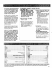
CAU1X)N
TO AVOID DAMAGE:
1, DO NOT CONNECT
SPEAKER OUTPUT
TO A SEPARATE
AMPLIFIER OR
TO SPEAKERS
CONNECTED TO
ANOTHER
PRODt_T.
2. DO NOT CONNECT
LEFT AND RIGHT
SPEAKER OUTPUTS
TOGETHER.
V_EO
INPUT
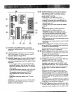
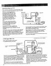
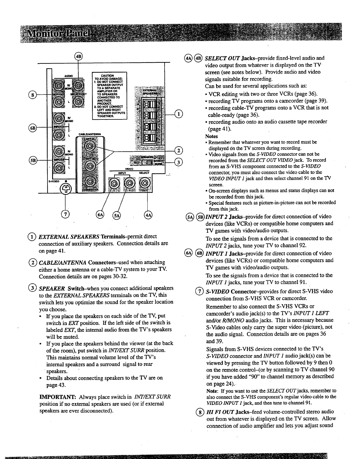
(_ EXTERNAL SPEAKERS Terminals-permit direct
connection of auxiliary speakers. Connection details are
on page 41.
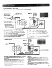
Q CABLE/ANTENNA Connectors-used when
attaching
either a home antenna or a cable-TV system to your TV.
Connection details are on pages 30-32.
Q SPEAKER Switch-when you connect additional speakers
to the EXTERNAL SPEAKERS terminals on the "IV, this
switch lets you optimize the sound for the speaker location
you choose.
• If you place the speakers on each side of the TV, put
switch in EXT position. If the left side of the switch is
labeled EXT, the internal audio from the TV's speakers
will be muted.
• If you place the speakers behind the viewer (at the back
of the room), put switch in INT/EXT SURR position.
This maintains normal volume level of the TV's
internal speakers and a surround signal to rear
•speakers.
• Details about connecting speakers to the TV are on
page 43.
IMPORTANT: Always place switch in INT/EXT SURR
position if no external speakers are used (or if external
speakers are ever disconnected).
@ SELECT OUT Jacks-provide
fixed-level audio and
video output from whatever is displayed on the TV
screen (see notes below). Provide audio and video
signals suitable for recording.
Can be used for several applications such as:
• VCR editing with two or three VCRs (page 36).
•-recording TV programs onto a camcorder (page 39).
• recording cable-TV programs onto a VCR that is not
cable-ready (page 36).
• recording audio onto an audio cassette tape recorder
(pag e 41).
Notes
• Remember that whatever you want to record must be
displayed on theTV screenduringrecording.
• Videosignals from the S-VIDEO connectorcan not be
recorded from the SELECTOUT VIDEOjack. Torecord
from an S-VHScomponent connectedto the S-VIDEO
connector,you must also connectthe videocable to the
VIDEOINPUT1 jack andthen selectchannel 91 on the TV
scween.
• On-screendisplayssuchas menus andstatus displays can not
be recorded from thisjack.
• Special features such as picture-in-picturecan not be recorded
from thisjack.
( )INPVT2Jacks-provide for direct connection of video
devices (like VCRs) or compatible home computers and
"IV games with video/audio outputs.
To see the signals from a device that is connected to the
INPUT2 jacks, tune your TV to channel 92.
@ @ INPUT 1 Jacks-provide for direct connection of video
devices (like VCRs) orcompatible home computers and
TV games with video/audio outputs.
To see the signals from a device that is connected to the
INPUT I jacks, tune your TV to channel 91.
Q S-VIDEO Connector-provides for direct S-VHS video
connection from S-VHS VCR or camcorder.
Remember to also connect the S-VHS VCRs or
camcorder's audio jack(s) to the TV's INPUT 1 LEFT
and/or R/MONO audio jacks. This is necessary because
S-Video cables only carrythe super video (picture), not
the audio signal. Connection details are on pages 36
and 39.
Signals from S-VHS devices connected to the TV's
S-VIDEO connector andINPUT I audio jack(s) canbe
viewed by pressing the TV button followed by 9 then 0
on the remote- control(or by scanning to TV channel 90
if you have added "90" to channel memory as described
on page 24)..
Note: Ifyouwanttousethe SELECT OUTjacks,rememberto
also connect the S-VHScomponent'sregularVideocable tothe
VIDEOINPUT1jack,andthen tuneto channel 91.
(_)HI FI OUT Jacks-feed volume-controlled stereo audio
out from whatever is displayed onthe TV screen. Allow
connection of audio amplifier and lets you adjust sound