


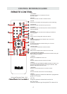
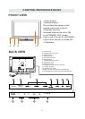
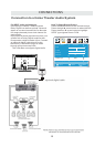

CONTROL REFERENCE GUIDE
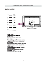
FRONT VIEW
5
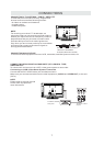
BACK VIEW
1.Color Screen
2.Remote Sensor
Do not block this sensor or the
remote control will not work.
3.Standby Indicator
Indicates whether the unit is ON
or in STANDBY (OFF) mode.
Light in red: The unit is in STANDBY.
Light in blue:The unit is turned ON.
4. Speakers
3
2
4
4
1
1
2
3
4
1.Power cord
2.Headphone OUT Jack
3.Service Port
4.HDMI IN Jacks
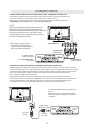
5.PC AUDIO IN Jack
6.VGA IN Jack
7.TV ANTENNA Terminal
8.Coax OUT Jack
9.VIDEO IN Jack
10.AUDIO L/R (AV/YPbPr) IN Jack
11.YPbPr IN Jack
12.AUDIO OUT Jack
(Audio out-This connection is forsending
out analog audio signal to the 2nd equipment.)
5
6
7
11
8
9 10
12
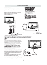
Head
phone
Service
Port
L -out- R