


6907-002013<00> 10-0361
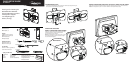
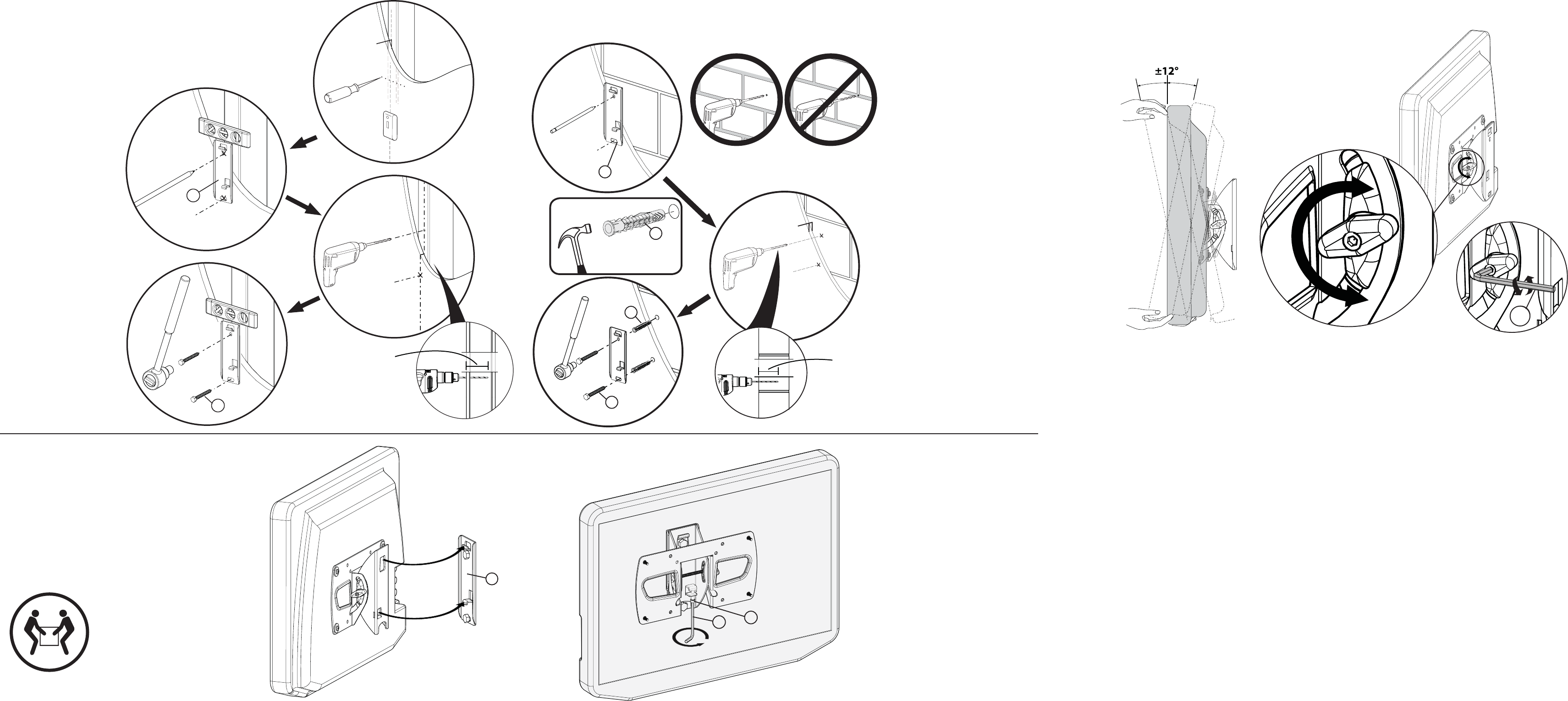
3 Install the wall plate
5 Adjust the tilt angle (if necessary)
H
H
G
B
< 16 mm
(
5
⁄8 in.
)
B
I
HEAVY! You will need
assistance with this step.
J
B
J
I
IMPORTANT SAFETY INSTRUCTIONS • SAVE THESE INSTRUCTIONS
Caution: Do not use this product for any purpose not explicitly specied by Rocketsh. Improper installation
may cause property damage or personal injury. If you do not understand these directions, or have doubts
about the safety of the installation, contact Customer Service or call a qualied contractor. Rocketsh is not
responsible for damage or injury caused by incorrect installation or use. The weight of your TV must not
exceed 50 lb (22.7 kg). The wall must be capable of supporting ve times the weight of the TV and wall
mount combined.
This product contains small items that could be a choking hazard if swallowed. Keep these items away from
young children!
5-year limited warranty
Visit www.rocketshproducts.com for details.
We’re here for you
www.rocketshproducts.com
For customer service, call:
800-620-2790 (U.S./Canada markets)
01 800-926-3010 (Mexico market)
© 2010 BBY Solutions, Inc., All Rights Reserved.
Distributed by Best Buy Purchasing, LLC 7601 Penn Avenue South, Richeld, MN USA 55423-3645
Best Buy Imports, S. de R.L. de C.V. Av. Santa Fe 485, Segundo Piso, Colonia Cruz Manca, Programa Parcial de Desarrollo
Santa Fe, Delegación Cuajimalpa, Distrito Federal, México 05349
ROCKETFISH is a trademark of BBY Solutions, Inc. Registered in some countries. All other products and brand names are
trademarks of their respective owners.
Option 1: Installing to a wood stud wall
Caution: Avoid potential injuries or property damage!
DO NOT over-tighten the lag bolts.
Any material covering the wall must not exceed 5/8 in. (16mm).
Option 2: Installing to a solid concrete or concrete block wall
Caution: Avoid potential injuries or property damage! DO NOT over-tighten the lag bolts.
Any material covering the wall must not exceed 5/8 in. (16mm).
a. Locate the stud. Verify the center of the stud with
an awl or thin nail or use an
edge-to-edge stud nder.
b. Level the wall plate (B)
and mark the hole
locations.
c. Drill the pilot holes
as illustrated.
d. Align the wall plate
with the pilot holes,
insert the lag bolts
(I) through the holes
in the wall plate, then
tighten the lag bolts
with a socket wrench
only until they are pulled
rmly against the wall
plate.
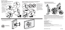
4 Mount the TV to the wall
a.Slide the TV/wall bracket assembly down over the
tabs on the wall plate (B), then tighten the locking
screw with the hex key (H).
a. Level the wall plate (B) and mark
the hole locations.
b. Drill the pilot holes as illustrated.
c. Insert the concrete wall anchors
(J) into the pilot holes and use a
hammer to make sure that the
anchors are seated ush with the
concrete surface.
d. Align the wall plate with the
anchors, insert the lag bolts (I)
through the holes in the wall
plate, then tighten the lag bolts
with the socket wrench only until
they are pulled rmly against the
wall plate.
You can adjust the tilt angle of the screen ± 12°.
If necessary, the tilt tension can be adjusted by tightening or
loosening the tension knob with either the hex key (H) or by
hand.
Caution: To prevent property damage
or personal injury, never drill into
mortar between blocks.
a.
b.
c.
d.
a.
a.
b.
c.
d.
75mm
3 in.
75mm
3 in.
< 16 mm
(
5
⁄8 in.
)