


INTRODUCTION
Thank you for your purchase of the CT 1 CABLE DETECTIVE cable
tester. This unit was designed with the working musician and sound
person in mind. Read the following manual carefully to ensure proper
operation and a full understanding of all the CT 1 functions.
Tests for: Opens
Shorts
Intermittents
Crossed wires
DESCRIPTION
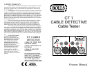
The CT 1 consists of two RCA jacks, two 1/4" jacks, two female XLR, two
male XLR jacks, and two MIDI jacks.
LED 1/GND: Indicates continuity between pins 1 of an XLR cable or MIDI
cable, or ground on an RCA or 1/4" cable.
LED 2/TIP: Indicates continuity between pins 2 of an XLR cable, or the tip
on an RCA or 1/4" cable.
LED 3/RING: Indicates continuity between pins 3 of an XLR cable or MIDI
cable, or the ring of a 1/4" cable.
To test RCA and 1/4" TS cables, plug each end of the cable into the proper jack
and wiggle the cable around at different points on the cable. Watch the 1 and 2
LEDs, if either LED is off, or goes on and off - the cable is bad.
The testing procedure for 1/4" TRS (stereo) and XLR cables is identical to the
above, except watch the 1, 2 and 3 LEDs.
Adapter type cables, such as 1/4" to XLR cables, may also be tested by plugging
each end into it's proper jack on either side of the line. Test as indicated above.
To test a MIDI cable, plug each end of the cable into the MIDI jacks and test as
described above. Watch the 1 and 2 LEDs, if either LED is off, or goes on and off
- the cable is bad.
NOTE: WHEN TESTING A 1/4" MONO TO RCA CABLE, CONNECT THE 1/4"
PLUG TO THE LEFT 1/4" JACK AND THE RCA TO THE RIGHT RCA JACK.
DUE TO A PARTICULAR CIRCUIT CONSIDERATION, TESTING VICE VERSA
(WITH THE 1/4" ON THE RIGHT AND THE RCA ON THE LEFT) WILL BE
INACCURATE.
TEST INDICATORS
NO LEDS = BAD CORD OR DEAD BATTERY
1 LED = SHORTED WIRES
2 LEDS = RCA, MIDI OR MONO CORD GOOD, OR CROSSED WIRES
IN STEREO & XLR CORDS
3 LED = GOOD STEREO 1/4" TRS, OR XLR CORD
CABLE DETECTIVE
CT 1
1/GND
2/TIP
3/RING
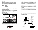
OPERATION
Insert one end of the cable to be tested on the left side of the line, located
in the middle of the CT 1, and the other side of the cable on the right side
of the line. See example below.
CABLE DETECTIVE
CT 1
1/GND
2/TIP
3/RING
122-Apr-1999
Document Number:
Date:
Sheet of
Ba
C A B L E T E S T E R C T 1
C T 1 . S C H
A
1 L E D = S H O R T E D W IR E S
2 L E D S = R C A , M O N O O R M ID I C O R D G O O D , O R C R O S S E D W IR E S IN S T E R E O & X L R C O R D S
+
M ID I T E S T
2 L E D S
B T 1
9 V
R 1
1 K
D 3
L E D
D 1
L E D
D 2
L E D
1 2
3
J 1
X L R F P C
J 7
P H O N E 1 /4
J 5
R C A P C
1 2
3
J 4
X L R F P C
J 6
P H O N E 1 /4
J 8
R C A P C
1 3
4
2
5
J 9
D IN 5
1 3
4
2
5
J 1 0
D IN 5
1 2
3
J 2
X L R J A C K M
12
3
J 3
X L R J A C K M
3 L E D S = G O O D S T E R E O 1 /4 "T R S , O R X L R C O R D
N O L E D S = B A D C O R D O R D E A D B A T T E R Y
R O L L S C O R P O R A T I O N
5 1 4 3 S o u t h M a in S t re e t
S a lt L a k e C it y , U T 8 4 1 0 7