


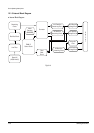
Circuit Operating Descriptions
Samsung Electronics 13-3
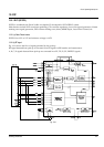
13-1-2 Circuit description [FLY-Back PWM(Pulse Width Modulation)] Control
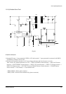
13-1-2 (a) AC Power Rectification/Smoothing Terminal
1) PDS01, PDS02, PDS03, PDS04 : Convert AC power to DC(Full wave rectification).
2) PER10 : Smooth the voltage converted to DC.
3) PCD01, PCD02, PBS01 : Noise removal at power input/output.
4) PVA1 : SMPS protection at power surge input.
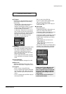
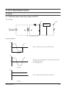
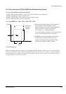
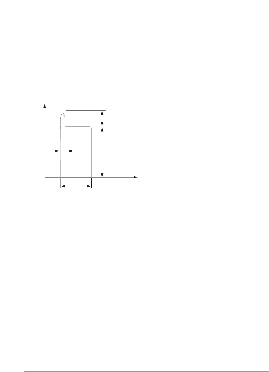
13-1-2 (b) SNUBBER Circuit : PDS11, PCD12, PRS13, PCD11, PPS12
0
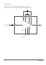
Vswitch
dt
Toff
t
Inverted power
by leakage
inductance
Fig. 13-7
1) Prevent residual high voltage at the terminals of
switch during switch off/Suppress noise.
High inverted power occurs at switch (PQR11) off,
because of the 1st winding of transformer :
(V=-L1 xdi/dt. L1 : Leakage Induction)
A very high residual voltage exist on both terminals
of PIC1 4, 5~8pin because dt is a very short.
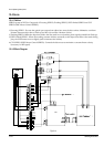
2) SNUBBER circuit protects PQR11 from damage
through leakage voltage suppression by RC,
(Charges the leakage voltage to PDS11, PER13,
PCD12 and discharges to PRS11, PRS12).
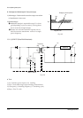
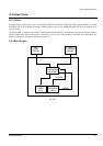
13-1-2 (c) Driving circuit
When Vin supplied, driving current Ig occurs throuhg the PICF1. By this I
1
(=Hfe x Ig) occurs throug the PIC1
and the Vb is inducted to base winding coil NB. By inducted Vb, Ib start flow and the V
CC
voltage of PQR11 is
sustained stable. Ib is constant and I
1
increases in Proportion to time. After constant time passed Ib become to
shortage and PIC1 is cut OFF (S/W OFF).