


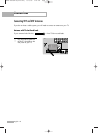
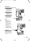
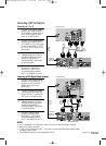
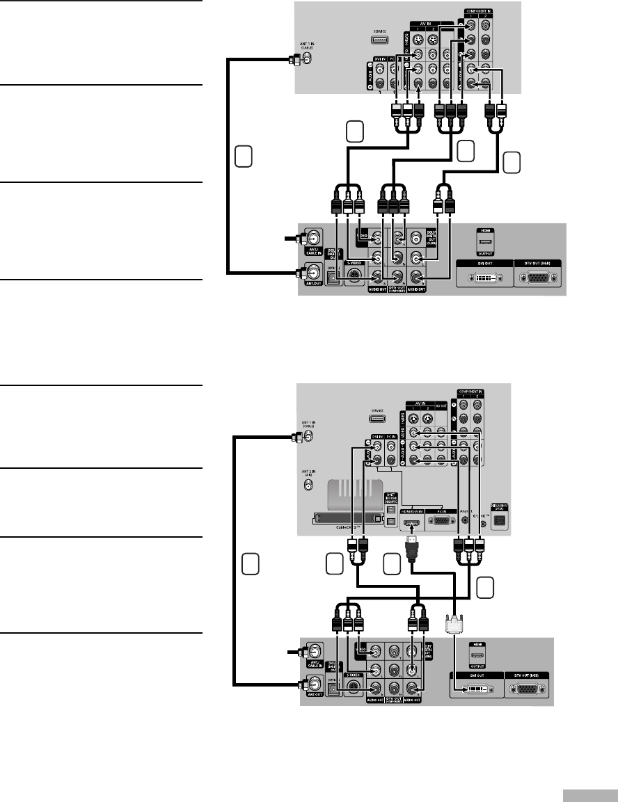
Connecting a DTV Set-Top Box
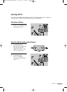
Connecting to Y, PB
, PR
1
Connect a set of audio cables
between the COMPONENT (1
or 2) AUDIO (L, R) IN jacks on
the TV and the AUDIO OUT
jacks on the Set-Top Box.
2
Connect a set of video cables
between the COMPONENT (1
or 2) VIDEO (Y, P
B
, P
R
) IN jacks
on the TV and VIDEO (Y/P
B
/P
R
or Y/C
B
/C
R
) OUT jacks on the
Set-Top Box.
3
Connect the Video/Audio
cables between the VIDEO or
S-VIDEO/AUDIO input jacks
on the TV and VIDEO or
S-VIDEO/AUDIO output jacks
on the Set-Top Box.
4
Connect a coaxial cable
between the Antenna out
terminal (i.e., “ANT.OUT”)
on the Set-Top Box and the
ANT 1 IN (CABLE) on the TV.
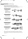
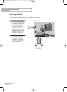
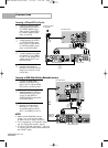
Connecting to DVI (Digital Visual Interface)
1
Connect a set of audio cables
between the DVI AUDIO (L, R)
IN jacks on the TV and the
AUDIO OUT jacks on the
Set-Top Box.
2
Connect an HDMI/DVI video
cable between the HDMI/DVI
IN jack on the TV and the DVI
OUT jack on the Set-Top Box.
3
Connect the Video/Audio
cables between the VIDEO or
S-VIDEO/AUDIO input jacks
on the TV and VIDEO or
S-VIDEO/AUDIO output jacks
on the Set-Top Box.
4
Connect a coaxial cable
between the Antenna out
terminal (i.e., “ANT.OUT”)
on the Set-Top Box and the
ANT 1 IN (CABLE) on the TV.
NOTES
• For an explanation of Component video, see your Set-Top Box owner’s manual.
• Requires a Cable Converter.
•To use the TV Guide On Screen
TM
, you have to connect both the Video/Audio cable
and the G-LINK
TM
cable.
• The HDMI/DVI IN jack is not compatible with PC.
English - 25
TV Rear Panel
DTV Set-Top Box
Incoming
Cable or
Antenna
TV Rear Panel
DTV Set-Top Box
Incoming
Cable or
Antenna
1
1
2
3
4
4
3
2
BP68-00469B-00(018~029) 10/24/05 11:26 AM Page 25