


4
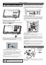
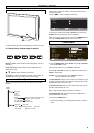
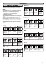
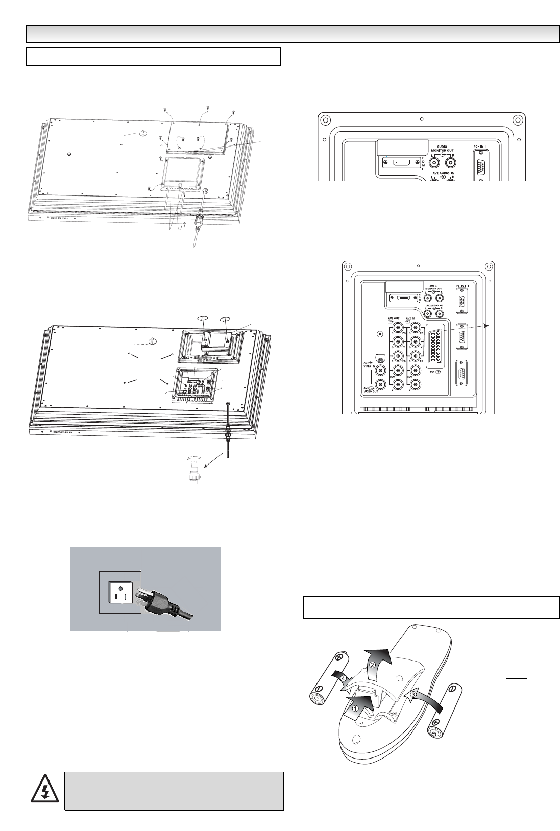
■ REMOVE TERMINAL COVER AS INDICATED BELOW.
■ CONNECT THE DISPLAY UNIT TO AERIAL, VGA. BNC.AND
PERITEL SCART CONNECTOR AS BELOW.
■ TERMINAL COVER MUST
BE REPLACED WITH CABLE EXITS AS
INDICATED IN THE SKETCH ABOVE.
■
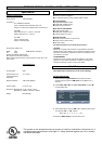
Connect the LCD monitor to VGA, and Scart connector as required.
1. Connect the waterproof in-line power connector to the connector
attached to the LCD monitor as shown above.
2. Connect the correct power cord of the LCD monitor to a wall outlet.
✐ As this product does not have a power On/Off switch, please
ensure your mains plug is easily accessible.
✐ The LCD monitor is prepared for a power voltage AC100 ~240V,
60Hz. To completely switch off the mains, or when the LCD
monitor is not to be used for an extended period of time, it is
advisable to disconnect the power cord from the power outlet or
disconnect thepower coupler.
3. Warning: To prevent injury, the unit must be securely attached to
the wall in accordance with the installation instructions.
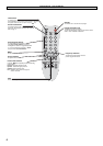
1.■ HDMI (High Definition Multimedia Interface)
This monitor has an HDMI connector. When connected to the HDMI
source and HDMI is selected using the remote control, there is a short
time period before the picture appears at a much higher resolution.
This connection is located at the back of the monitor next to the aerial
socket.
2. Y,Pb,Pr connection (AV2)
This LCD monitor has a choice of Y, Pb, Pr or RGB , H/V connections
You can connect your DVD player to the Y, Pb, Pr terminals instead
of using a scart lead. This can support high definition in analogue
component form. RGB, H/V can be used as a PC input via the BNC
terminal.
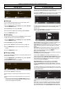
3. PC connection
This display unit has a PC connector. You can connect a PC to the
Display unit and use it as a monitor (see page 7).
To switch between TV, AV1, RGB, AV2 RGB H/V or Y, Pb, Pr, AV3,
HDMI or PC mode press the TV/AV switch on your remote control
repeatedly or press and hold the the TV/AV button for a few seconds
and selection menu will appear on screen use the e or d buttons to
select the correct mode.
4
. RS232C IN/OUT: Is an input for external commands to control the
monitor (see page 8). Use the switch to change between AV/ RS232/
PJ net
5
.
PJ/PD Net IN/OUT: Has the ability for PJ-NET(or PD-net) to be
connected to control the monitor using a network (switch is in).
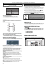
Install two "AA" 1.5 volt batteries so that the "+" and "-" marks on the
batteries match the "+" and "-" marks inside the unit into the remote
control handset.
INST
INST
ALLA
ALLA
TION
TION
Step : 1 Connections (Essential)
WARNING! High voltages are used in the operation of
this set. Refer service to qualified service personnel.
Security Fixing point
Cable entry
PJ-Net
Cable entr
y
Step : 2 Remote control battery installation
Security fixing point
Wall
mount
fixing
positions
HDMI
Audio monitor
Out
AV2 audio
IN
Serial ports
IN/ Out
Services
AV3 IN/Out
BNC
AV2 IN/ Out
BNC
Switch
RS232C
PJ Net box
Waterproof in-line connector
WARNING!
This remote
control is
not
waterproof
Serial
Port-IN
Serial
Port-OUT
Service
Peritel (Scart)