


11
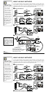
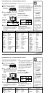
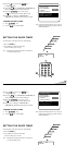
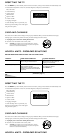
USING THE AUDIO/VIDEO INPUT JACKS
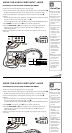
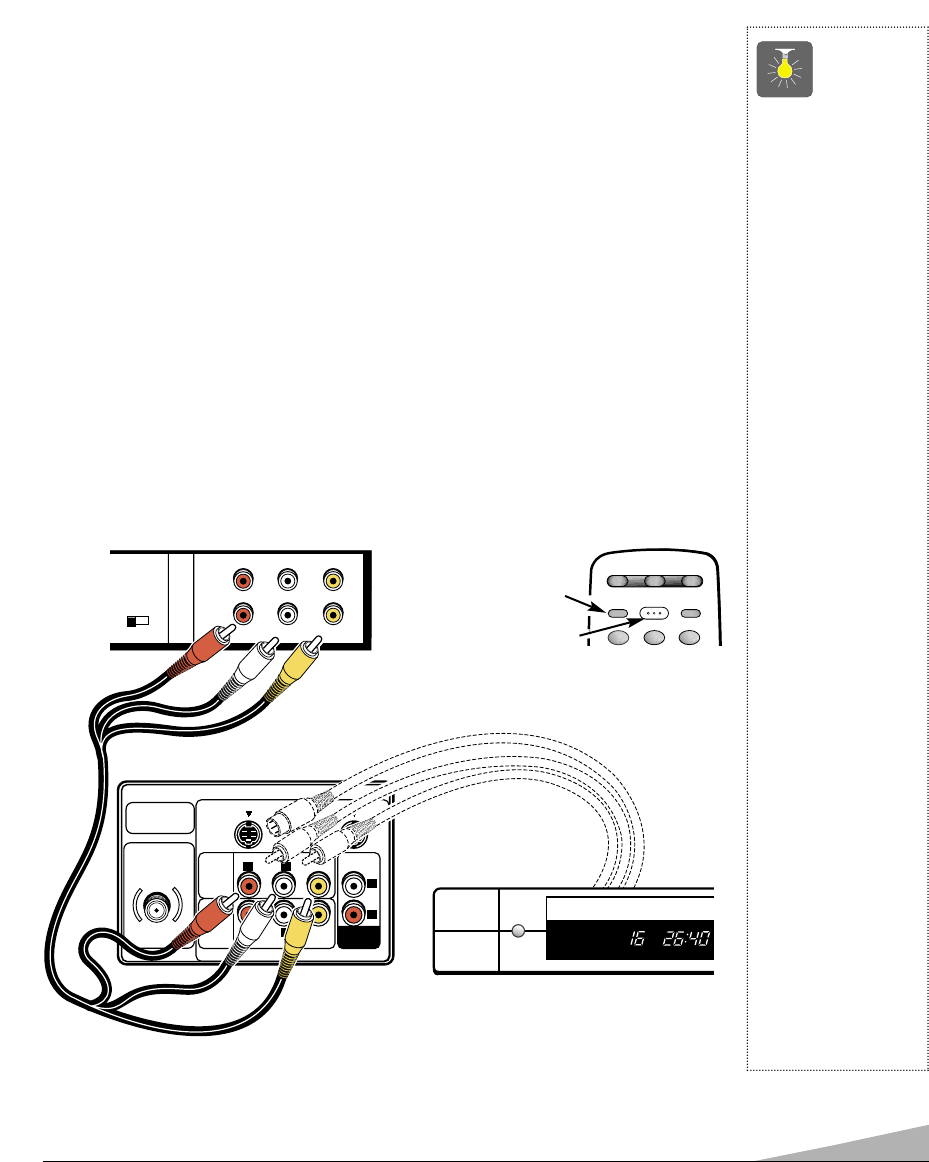
CONNECTING A VCR OR OTHER EXTERNAL EQUIPMENT
Switch off TV and external equipment before connecting cables.
1. Connect VCR, DVD, DSS, or other equipment’s Audio Out (R/L) to the TV Audio Input (R/L)
❶
.
For Mono VCR (Single Audio Jack) connect VCR Audio Out to TV Audio (L) Input.
2. Connect VCR, DVD, DSS, or other equipment’s Video Out to the TV Video Input
❷
.
Optional
Connect VCR, DVD, DSS, or other equipment’s S-Video Out to the TV S-Video In 1 Jack ➁.
Using the S-Video In 1 jack overrides the Video 1 jack
❷
.
For model AVM-3650G only, using the S-Video In 2 jack overrides the Video2 Input jack ➁.
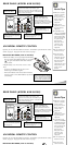
3. Press POWER to turn on the TV. See
❸
. Turn on external equipment also.
4. Press the VIDEO MODE key
❹
to select program source: TV signal or signal from the
equipment you have connected to the A/V1 and A/V2 jacks. See
❹
and page 6 for
remote control operation
.
Follow the same procedure to connect other compatible video equipment to the second set
of A/V jacks.
QuickTips
■
Make sure all cable
connectors are fully
seated on jacks.
■
Always match cables
according to the
colors;
RED for right
audio,
WHITE for left
audio and
YELLOW
for video.
■
A/V1 and A/V2 jacks
have identical func-
tions. Any
compatible video
equipment can be
connected to either
set of jacks.
■
A solid Blue screen
with the word
Video1 or Video2
displayed means
that the Video mode
is selected, but no
signal is being
detected at the
Video jack. Check
connection, and
turn on external
equipment.
■
Make sure you select
TV channel to match
your VCR output
(Ch. 3 or 4).
■
You may be able
to use the remote
control to operate
your VCR, Cable
Box and TV.
(See page 7.)
UHF/VHF/CATV
75Ω
AUDIO VIDEO
(MONO)
R
L
LR
AUDIO VIDEO
(MONO)
LR
S-VIDEO IN -1
AUDIO
VIDEO
INPUT
1
S-VIDEO IN -2
AUDIO
VIDEO
INPUT
2
AUDIO
OUTPUT
CH3 CH4
IN
OUT
A/V JACKS
RF
CHANNEL
R- -L
AUDIO VIDEO
R- -LAUDIO VIDEO
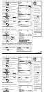
Back View
of a VCR
❷
➊
1
2 3
RESET
VIDEO
MODE
POWER
CABLEVCR TV
❹
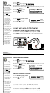
Remote Control
❸
TV A/V Input
Rear Jacks
DVD Player
➁
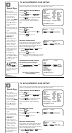
USING THE AUDIO/VIDEO INPUT JACKS
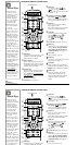
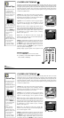
CONNECTING A VCR OR OTHER EXTERNAL EQUIPMENT
Switch off TV and external equipment before connecting cables.
1. Connect VCR, DVD, DSS, or other equipment’s Audio Out (R/L) to the TV Audio Input (R/L)
❶
.
For Mono VCR (Single Audio Jack) connect VCR Audio Out to TV Audio (L) Input.
2. Connect VCR, DVD, DSS, or other equipment’s Video Out to the TV Video Input
❷
.
Optional
Connect VCR, DVD, DSS, or other equipment’s S-Video Out to the TV S-Video In 1 Jack ➁.
Using the S-Video In 1 jack overrides the Video 1 jack
❷
.
For model AVM-3650G only, using the S-Video In 2 jack overrides the Video2 Input jack
➁.
3. Press POWER to turn on the TV. See
❸
. Turn on external equipment also.
4. Press the VIDEO MODE key
❹
to select program source: TV signal or signal from the
equipment you have connected to the A/V1 and A/V2 jacks. See
❹
and page 6 for
remote control operation
.
Follow the same procedure to connect other compatible video equipment to the second set
of A/V jacks.
QuickTips
■
Make sure all cable
connectors are fully
seated on jacks.
■
Always match cables
according to the
colors;
RED for right
audio,
WHITE for left
audio and
YELLOW
for video.
■
A/V1 and A/V2 jacks
have identical func-
tions. Any
compatible video
equipment can be
connected to either
set of jacks.
■
A solid Blue screen
with the word
Video1 or Video2
displayed means
that the Video mode
is selected, but no
signal is being
detected at the
Video jack. Check
connection, and
turn on external
CH3 CH4
IN
OUT
A/V JACKS
RF
CHANNEL
R- -L
AUDIO VIDEO
R- -LAUDIO VIDEO
Back View
of a VCR
➊
1
2 3
RESET
VIDEO
MODE
POWER
CABLEVCR TV
❹
Remote Control
❸