VOL
—
VOL
+
GUIDE
RECORD
EXIT LISTINFO
CH
+
POWER
1 2 5673 4 128 91011 13 1
CH
—
T9995
T10490
ET
H
E
RN
ET
U
S
B
LR
THIS DEVICE IS INTENDED TO BE ATTACHED
TO A RECEIVER THAT IS NOT USED TO
RECEIVE OVER-THE-AIR BROADCAST
SIGNALS. CONNECTION OF THIS DEVICE
IN ANY OTHER FASHION MAY CAUSE
HARMFUL INTERFERENCE TO RADIO
COMMUNICATIONS AND IS IN VIOLATION
OF THE FCC RULES, PART 15.
AVI S:
RISQUE DE CHOC
ELECTRIQUE NE PAS OUVRIR
120 VAC
60HZ 5A
120 VAC
60HZ 80W
AUDIO
VIDEO
S-VIDEO
OUT
CAU
TIO
N
RISK OF ELECTRIC SHOCK
DO NOT OPEN
CABLE
IN
INPUT (AUX)
OUT 2
(VCR)
OUT 1
(TV)
1394 1394
CATV CONVERTER
MADE IN MEXICO
CABLE
OUT
24 10931
IR
1211
DIGITAL
AUDIO OUT
0003B4287797
SABDQXTL N0006246618
5 6 7 8
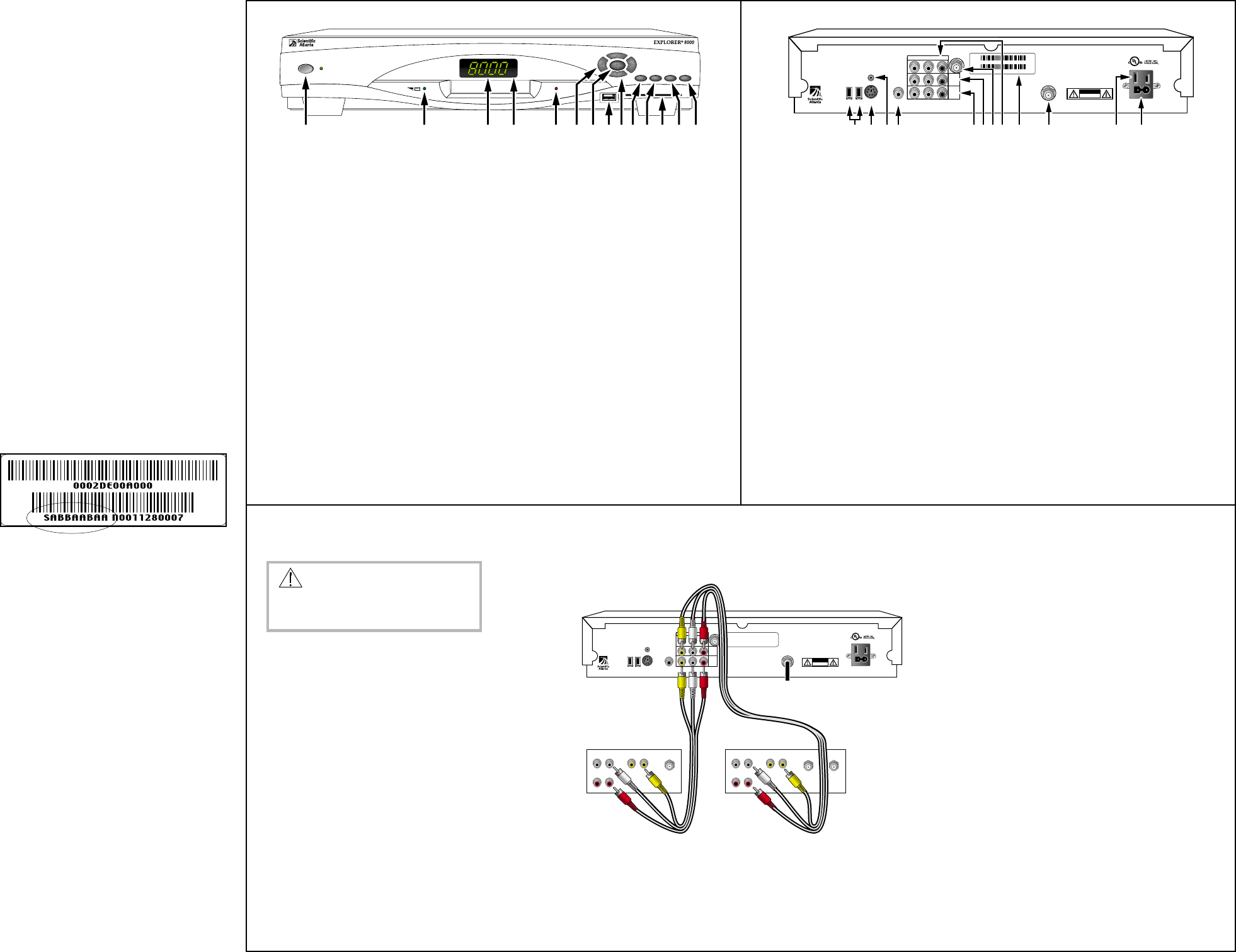
1 Power Provides power to the Explorer 8000. The light to the right of the
Power key illuminates when the power is on.
2 Message Indicator Indicates a message is waiting for you from your cable service provider.
The indicator is either blinking or illuminated. To access the message,
press the Info key
3 LED Display Displays the selected channel number or time of day
4 IR Sensor Receives the infrared signal from the remote
5 Recording Indicator Indicates the DVR feature is active when illuminated
6 VOL+ and VOL- Increases and decreases volume
7 Select Accesses your on-screen selection
8 USB Connects to external equipment, such as a keyboard or similar equipment.
(Universal Serial Bus) This connector is reserved for future use and may not be available on all
Explorer 8000 models.*
9 CH+ and CH- Scrolls up and down through the channels
10 Guide Accesses on-screen services, such as the on-screen guide,
video-on-demand, or pay-per-view
11 Info Displays a description of the selected program; available from the
on-screen guide and while viewing a program
12 Smart card slot Allows smart card access. (Contact your cable service provide for more
information.)
13 Exit Exits menus, on-screen guide, and program information
14 List Accesses list of recorded programs displayed on the TV screen
Entertainment Server Back Panel
Installing the Entertainment Server
Getting Started
Congratulations for adding the Explorer
®
8000
Home Entertainment Server to your television
viewing experience!
The Explorer 8000 Home Entertainment Server is
equipped with the following Digital Video
Recorder (DVR) and picture-in-picture (PIP)
features:
• A DVR feature to record a TV program while
you view a different program or to record two
programs simultaneously
• A PIP feature to simultaneously view another
program even if your TV does not have PIP
capability
Use the instructions in this guide to install the
Entertainment Server, to become familiar with the
keys on the front panel of the Entertainment
Server, and to access your cable services. Then,
begin enjoying the features of the Entertainment
Server.
Explorer eClub
To obtain additional information about the
Entertainment Server, Scientific-Atlanta invites
you to join the Explorer eClub. This online club
provides news and “what’s up” information about
the Entertainment Server and offers you a chance
to win premium items.
To join the Explorer eClub, you must know the
serial number of your Entertainment Server. The
serial number is on a bar code on the back of the
Entertainment Server and looks similar to this
example:
Entertainment Server Front Panel
1. Unplug all electronic devices before connecting the
Entertainment Server.
2. Connect the Entertainment Server to the stereo TV
as shown in the diagram.
3. Connect the Entertainment Server to the coaxial
cable coming from the wall.
4. Plug the Entertainment Server and the TV into an
AC power source.
Important: Do not press the Power key on the
Entertainment Server yet.
5. Turn on the power to your TV, and set the input
channel assigned by your cable service provider.
6. Wait for the time to display on the LED display.
Important: It takes 2 to 3 minutes for the Enter-
tainment Server to be updated with the latest
programming and service information. When the
front panel displays the time, the update is
complete.
7. Press the Power key on the Entertainment Server.
Access cable services and programs by pressing
the following keys on the front panel of the
Entertainment Server or on the remote control.
(Refer to your remote control user’s guide for
programming instructions.)
• Guide — Access the on-screen guide. The
on-screen guide displays schedules of TV
programs and other services available from your
cable service provider, such as video-on-demand
and pay-per-view programs.
• Arrows — Highlight a program in the schedule.
• Info — Display the description of a specific
program (either from the on-screen guide or
while viewing a program).
• Select — View a specific program in the guide.
For more information, read the user’s guides that
your cable service provider included with the
Entertainment Server installation package. These
guides provide operating instructions for the
on-screen guide, your remote control, and the VCR
Commander™ service (if available).
If your Entertainment Server does not perform
as expected, check the following conditions:
• Verify that the power to your TV is turned on.
• Verify that the smart card is inserted in the
front slot of your Entertainment Server (if
required by your cable service provider).
• If plugged into a wall switch, verify the switch
is in the ON position.
• Verify that all cables are properly connected.
• Verify that your TV is tuned to the proper
output channel (3 or 4).
• Verify that the Entertainment Server power
light is on.
If the Entertainment Server does not perform as
expected after checking the power, the cables,
and the output channel, check the following
conditions:
No picture
• If your system includes a VCR and/or stereo
system, verify that you have properly
connected them to the Entertainment Server.
No color
• Verify that the current TV program is broadcast
in color.
• Adjust the TV color controls.
No sound
• If your setup includes a VCR and/or stereo,
verify that you have properly connected them
to the Entertainment Server.
• Verify that the volume is turned up.
• Verify that the mute function is not engaged.
The channel number on the LED flashes.
Press Info on the remote control or the front panel
of the Entertainment Server. You may have
pressed the Power key before the Entertainment
Server received all of the latest programming
updates.
The TV screen displays a message indicating
that the Entertainment Server is automati-
cally updating its software.
Wait for the time to display on the LED before
continuing with the installation process. When the
front panel displays the time, the update is
complete.
Note: If you need further assistance, contact your
cable service provider.
Accessing Programs
The serial number begins with SA and is located
in the lower left corner of the bar code. Write the
serial number here: _______________ .
You can access the Explorer eClub on the
Internet at the following Web address:
www.scientificatlanta.com/explorerclub
Before Installing the Entertainment
Server
• Read the IMPORTANT RULES FOR SAFE
OPERATION section of this guide.
• Locate the serial number, which is on a bar
code on the back panel of the Entertainment
Server. You will need this serial number to join
the Explorer eClub. Also, your cable service
provider may need to know this serial number
to provide technical assistance.
• If you plug the Entertainment Server into an
outlet that is controlled by a wall switch,
keep the switch in the ON position. The
on-screen guide is updated nightly. If the wall
switch is in the OFF position, your Entertain-
ment Server will not receive the latest
programming updates.
• Keep the top of the Entertainment Server free
of all objects and electronic devices, including
your TV.
• It is recommended that you use a surge
protector with your cable equipment and
electronic devices.
WARNING:
Electric shock hazard! Unplug all
electronic devices before connecting
or disconnecting any device cables.
1 1394 Connects to optional 1394-equipped (fire wire) devices.
This connector is reserved for future use and may not be available on all
Explorer 8000 models.*
2
S-Video Out Connects to S-Video input of TV or VCR (standard definition)
3 IR Port Connects to optional VCR Commander service
4 Digital Audio Out Connects to external digital input surround-sound receiver
5 TV Out Connects to video and left/right (L/R) audio inputs of a TV
(standard definition). The video outlet is also referred to as
COMPOSITE video
6 VCR Out Connects to video and left/right (L/R) audio inputs of a VCR
7 Cable Out Connects to cable input of TV or VCR (standard definition)
8 Auxiliary Input Connects to video and left/right (L/R) audio output of external
device
9 Serial Number Located in the lower left corner of the bar code. Your cable service
provider may ask for this number if your system requires troubleshooting
in the future. You must know the serial number to join the Explorer eClub
10 Cable In Connects to cable signal from cable service provider
11 AC Switched Outlet Connects the AC power cord from another device, such as a TV
12 AC Power Input Connects the Entertainment Server to an AC electrical outlet
Connect the Entertainment Server to a Stereo TV and Stereo VCR
To listen to stereo sound, you must do one of the
following:
• Connect stereo audio cables from the AUDIO
OUT LEFT and RIGHT connectors on the
Entertainment Server to the AUDIO IN LEFT
and RIGHT connectors on your stereo TV.
• Connect an RCA cable (not shown) from the
DIGITAL AUDIO OUT on your Entertain-
ment Server to the DIGITAL AUDIO IN on
your stereo receiver.
In addition, you may also connect an S-video
cable from the S-VIDEO OUT connector on the
Entertainment Server to the S-VIDEO connector
on the stereo TV or VCR. (This connection is not
shown.) However, the S-video connection does
not supply audio. You must also use audio cables
with the S-video cable.
Stereo Sound
Different TV Connectors
If your TV has different connectors from the ones
shown here, or if you are connecting the Enter-
tainment Server to additional devices, access our
Web site for connection information at the
following address:
www.scientificatlanta.com
ETHERNET
USB
LR
THIS DEVICE IS INTENDED TO BE ATTACHED
TO A RECEIVER THAT IS NOT USED TO
RECEIVE OVER-THE-AIR BROADCAST
SIGNALS. CONNECTION OF THIS DEVICE
IN ANY OTHER FASHION MAY CAUSE
HARMFUL INTERFERENCE TO RADIO
COMMUNICATIONS AND IS IN VIOLATION
OF THE FCC RULES, PART 15.
AVI S:
RISQUE DE CHOC
ELECTRIQUE NE PAS OUVRIR
120 VAC
60HZ 5A
120 VAC
60HZ 80W
AUDIO
VIDEO
S-VIDEO
OUT
CAUTION
RISK OF ELECTRIC SHOCK
DO NOT OPEN
CABLE
IN
INPUT (AUX)
OUT 2
(VCR)
OUT 1
(TV)
1394 1394
CATV CONVERTER
MADE IN MEXICO
CABLE
OUT
IR
DIGITAL
AUDIO OUT
T10491
CABLE/
ANTENNA
RIGHT
INOUT
LEFT
AUDIO
INOUT
VIDEO
INOUT
OUT TO
TV
IN FROM
ANTENNA
RIGHT
INOUT
LEFT
AUDIO
INOUT
VIDEO 1
INOUT
Cable Input
TV VCR
* Contact your cable service provider for more information.


