


English - 10 -
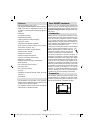
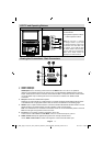
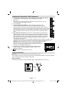
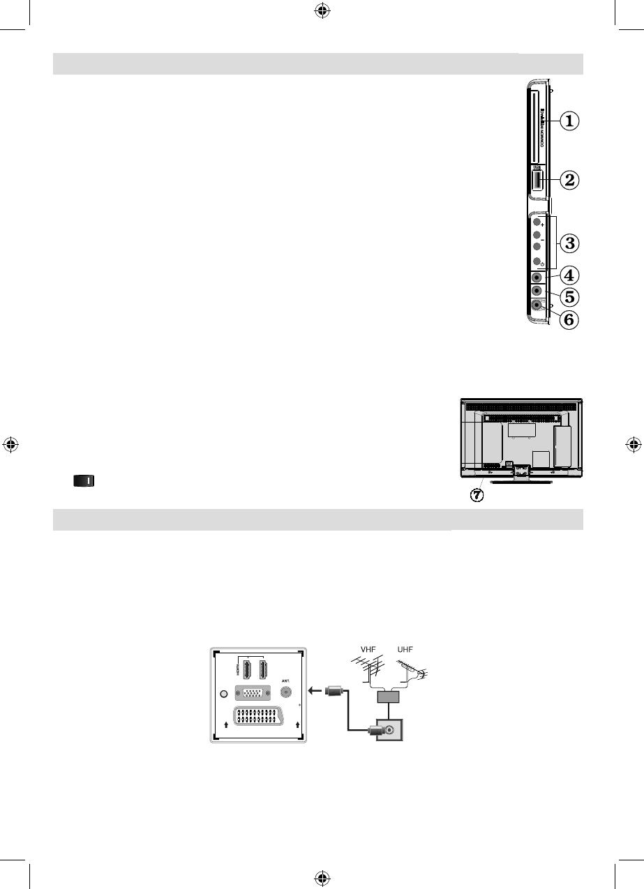
Viewing the Connections - Side Connectors
CI Slot is used for inserting a CI card. A CI card allows you to view all the channels that 1.
you subscribe to. For more information, see “Conditional Access” section.
USB Inputs. 2.
Note that programme recording feature is available via these USB inputs. You can
connect external hard disk drives to this input.
TV control buttons.3.
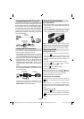
Component Video Input (YPbPr)4. is used for connecting component video.
You can connect the component video and audio sockets with a device that has
component output. To do this, you must use the supplied component video connection
cable for enabling connection. First, plug single jack of the cable to the TV’s YPbPr socket
(side). Afterwards, insert your component cable’s (not supplied) connectors into the plural
part of the Component video connection cable. Colours of the connected jacks should
match.
Side audio-video connection5. input is used for connecting video and audio signals of
external devices. To make a video connection, you must use the supplied AV connection
cable for enabling connection. First, plug singular jack of the cable to the TV’s Side AV
socket. Afterwards, insert your video cable’s (not supplied) connector into the YELLOW
input (located on the plural side) of the supplied AV connection cable. Colours of the
connected jacks should match.
To enable audio connection, you must use RED and WHITE inputs of the side AV connection cable.
Afterwards, insert your device’s audio cable’s connectors into the RED and WHITE jack of the
supplied side AV connection cable. Colours of the connected jacks should match.
Note: You should use audio inputs of side AV connection cable (RED &
WHITE) to enable sound connection when connecting a device to your TV
by using PC or COMPONENT VIDEO input.
Headphone jack is used for connecting an external headphone to the 6.
system. Connect to the HEADPHONE jack to listen to the TV from
headphones (optional).
7. , switch is used for turning the TV on or off.
Power Connection
IMPORTANT: The TV set is designed to operate on 220-240V AC, 50Hz.
After unpacking, allow the TV set to reach the ambient room temperature before you connect the set to the •
mains. Plug the power cable to the mains socket outlet.
Aerial Connection
Connect the aerial ,cable TV plug to the AERIAL INPUT socket located at the rear of the TV.•
SPDIF
SCART
VGA
Coax.OUT
1
2
USB
5Vdc
Max:500mA
P\V-AV
SIDE AVYPbPr
00_MB60_[GB]_1910UK_IDTV_PVR_NICKEL16_24942LED_YPBPR_ROCKER_10072638_5018xxxx.indd 1000_MB60_[GB]_1910UK_IDTV_PVR_NICKEL16_24942LED_YPBPR_ROCKER_10072638_5018xxxx.indd 10 22.07.2011 16:56:2722.07.2011 16:56:27