


SETTING FOR RS-485 OR RS-232C USE
The RS-485 interface can be used to operate the VCR
using a SANYO brand system controller. Furthermore,
the RS-232C interface can be used to operate the VCR
using a computer.
NOTES:
œ This can only be used when the RS-485/232C
interface board (VZU-485/232C) is installed.
œ Refer to the instruction manuals for the
VZU-485/232C, the system controller and/or the
computer.
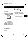
Setting the Address and Data Transfer
Speed
œ Make this setting without a cassette tape inserted.
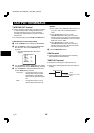
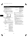
1
Press the COUNTER RESET button for 3 seconds
or more.
ø “485” or “232” appears on the digital display.
2
Turn the JOG dial to select the interface being used,
RS-232C or RS-485.
ø “232” or “485” appears on the digital display.
œ When setting “232”, carry out step 3 and then
step 6.
3
Turn the SHUTTLE ring clockwise.
4
Turn the JOG dial to set the VCR address (from 000
to 127).
ø The address set appears on the digital display.
5
Turn the SHUTTLE ring clockwise.
6
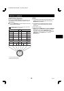
Turn the JOG dial to set the data transfer speed
(19200, 2400, 4800, 9600).
ø The data transfer speed set appears on the
digital display.
7
When finished, Press the COUNTER RESET button.
NOTE:
œ When the MENU RESET button is pressed, the
setting appearing on the digital display is reset to the
default setting.
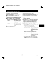
Settings when using RS-485
1
Press the MENU button to display the MAIN MENU.
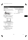
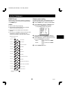
2
Turn the JOG dial to select the “9.OTHERS” line,
then turn the SHUTTLE ring clockwise.
ø The (OTHERS) menu appears.
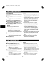
<OTHERS>
*ALARM@LOG
*POWER@FAILURE/DEW
*TERMINAL@SET@@@@SET1
*RS-485@SET
@@STATUS@INFO.@@@Y
@@ALARM@INFO.@@@@Y
3
Turn the JOG dial until the “STATUS INFO.” setting
is highlighted, then turn the SHUTTLE ring clockwise.
4 Turn the JOG dial to set the “STATUS INFO.”
setting, then turn the SHUTTLE ring clockwise.
Y. . . . . . . . . . The VCR status information is
output at the RS-485 connector.
N . . . . . . . . . The status information is not
output at the RS-485 connector.
5 Turn the JOG dial until the “ALARM INFO.” setting is
highlighted, then turn the SHUTTLE ring clockwise.
6
Turn the JOG dial to set the “ALARM INFO.” setting,
then turn the SHUTTLE ring clockwise.
Y. . . . . . . . . . The VCR alarm information (alarm
recording start and stop) and
video loss information are output
at the RS-485 connector.
N . . . . . . . . . The VCR alarm information (alarm
recording start and stop) and
video loss information are not
output at the RS-485 connector.
7
Press the MENU EXIT button.
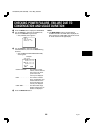
8
Set the TERMINATE switch on the back panel to the
“ON” or “OFF” position
OFF side . . . Not terminated
ON side . . . . Terminated
NOTE:
œ When a warning state (non-recording, mechanical
problem or clog detection) occurs, the warning state is
output from the RS-485 connector. However,
non-recording warning states are not output if “NON
REC” is set to “N” in the (WARNING OUT/CONTROL
SET) menu. In addition, the clog detection warning
state is not output if “CLOG DETECT.” is set to “N” in
the (GENERAL SET) menu.
RF4QR/NA (SRT-8960 GB) Wed. May, 08/2002
English
43