


3
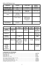
Operating Temperature Range
-7° to 49° C NOTE: Battery characteristics may limit this range
Overall Dimensions
U1: 92.2 mm L x 64.7 mm W x 24.2 mm D
U2/58:228.6 mm L x 51 mm Dia.
U2/BETA 58: 220.9 mm L x 51 mm Dia.
U2/SM86: 213 mm L x 49 mm Dia.
U2/87: 223.5 mm x 51 mm Dia.
U2/BETA 87A, U2/BETA 87C: 228 mm L x 50 mm Dia
U4S/U4D: 44.5 mm H x 482.6 mm W x 295.3 mm D
Net Weight
U1: 175.2 g without battery
U2/58, U2/BETA 58: 330 g without battery
U2/86: 332 g without battery
U2/87, U2/BETA 87A, U2/BETA 87C: 339 g without battery
U4S: 3.30 kg
U4D: 3.85 kg
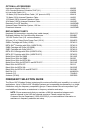
Certification
U1, U2: Type Accepted under FCC Part 74. FCC ID DD4U1M4 and DD4U2M4. Certified by IC
in Canada under RSS-123 and RSS-102
U4S, U4D: UL and cUL Listed to UL 6500, 2nd Edition and CAN/CSA E60065-00. Approved
under the Declaration of Conformity provision of FCC Part 15; Certified by IC in Canada under
RSS-123 & ICES-003 VDE Certified to EN 60065, 6th Edition.
UHF Type Approved and EMC Approved systems. Meet the requirements of 300.422-1,-2 and
301 489 Parts 1 and 9 and are eligible to carry the CE marking.
FCC Statement
The U4 Receiver complies with Part 15 of the FCC rules. Operation is subject to the following
two conditions: (1) this device may not cause harmful interference, and (2) this device must ac-
cept any interference received, including interference that may cause undesired operation.
Licensing Statement
A user license may be required for operation. Contact the communications authority in your
country for more information.
Modifications to Approved Equipment
Changes or modifications not expressly approved by Shure Incorporated could affect compli-
ance with telecommunications standards, thereby voiding the user's authority to operate this
product.
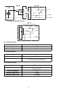
U1 Transmitter Input (Figure 1A, 1B, 1C)
Connector: 4-Pin Male Miniature Connector (TA4M) or
LEMO connector (optional)
Input Configuration: Unbalanced, active
Actual Impedance: 18 kW with lavalier microphone
1 MW with instrument cable
Maximum Input Level: 6 Vp-p (+7 dBV) using 1 kHz signal for 1% THD at
minimum gain setting with -6 dB pad.
4-Pin Male Miniature Connector
TA4M Pin Assignments:
Pin 1: Tied to Ground
Pin 2: Tied to +5 V
Pin 3: Tied to Audio
Pin 4: Tied thru 20 kW Resistor to Ground.
(On instrument adapter cable, Pin 4 floats).
See Figure 1B
LEMO Connector
Pin Assignments:
Pin 1: Tied to Pin 3 and 10 kW to Ground
Pin 2: +5V
Pin 3: Tied to Pin 1
Pin 4: Tied to Shield (Ground for Positive Bias).
See Figure 1C
Voltage for Remote Power: +5 V supplied to microphone cartridge
O682