


17
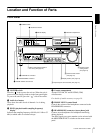
Location and Function of Parts
Chapter 1 Overview
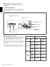
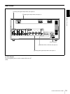
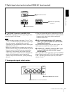
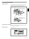
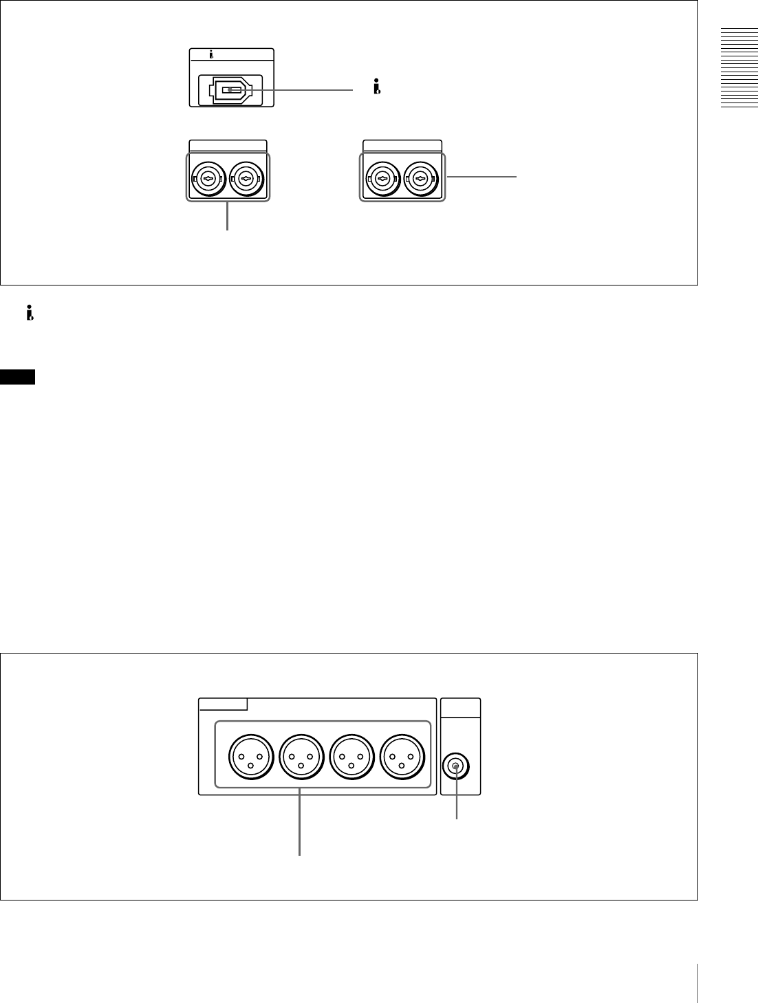
B Digital signal output section (optional DSBK-1601 board required)
a DV IN/OUT connector (6-pin IEEE-1394)
This i.LINK-compatible connector outputs digital video
and audio signals in DV format.
Note
• When searching at speeds in the range +
1
/
2
to +
1
/
30
or
−
1
/
2
to −
1
/
30
times normal speed, the audio signal output
from this connector and monitored on external
equipment may sound differently from the audio signal
played back on this unit.
• When you connect this unit to another device with a 6-
pin DV connector, always power the other device off and
unplug its power cord from the power output before
connecting or disconnecting the i.LINK cable (DV
cable). If you connect or disconnect the cable with the
power cord still plugged in, power from the DV
connector may flow into this unit, possibly damaging
this unit.
• When you connect this unit to another device with a 6-
pin DV connector, make the connection to the 6-pin DV
connector on the other device before making the
connection to this unit.
b SDI (Serial Digital Interface) OUT connectors
(BNC type) (optional DSBK-1601 SDI/AES/EBU
Output Board required)
Output SDI-format digital video and audio signals. The
same signals are output from both connectors.
c AUDIO OUT (AES/EBU) connectors (BNC type)
(optional DSBK-1601 SDI/AES/EBU Output
Board required)
These connectors output digital audio signals in AES/EBU
format. The left connector (CH-1/2) is for audio channels
1 and 2, and the right connector (CH-3/4) is for audio
channels 3 and 4.
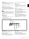
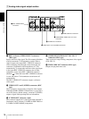
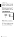
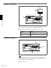
C Analog audio signal output section
AUDIO OUT(AES/EBU)
DV IN/OUT
CH-1/2
1
2
CH-3/4
SDI OUT
a DV IN/OUT connector
3 AUDIO OUT (AES/EBU)
connectors
2 SDI OUT connectors
MONITOR
OUT
AUDIO
AUDIO OUT
CH-1
CH-2 CH-3
CH-4
b AUDIO MONITOR OUT connector
a AUDIO OUT CH-1 to CH-4 connectors