


30
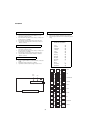
KV-29FX11
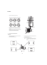
A
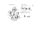
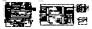
TUNER / IF
RV01
RV02 LV01
TP1
V SIZE
V LIN
S CORRECTION
V CENTRE
H SHIFT
H SIZE
PIN AMP
TILT
CORNER PIN
V ANGLE
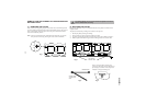
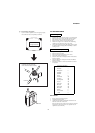
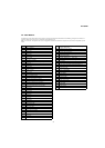
SYSTEM B/G, D/K, I & L I.F ADJUSTMENT
1. Input an off air signal of between 60-100dBuV / 75 ohm
terminated, via the tuner socket.
2. Enter into the ‘IF Adjustment’ service mode [i.e ‘TT59’] to fix
the I.F frequency to 39.9MHz.
3. Enter into the service mode and select ‘Current TV status’.
4. Adjust the I.F coil [LV01] until the ‘AFT Status’ indicates a
‘Window’ condition.
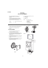
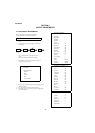
SYSTEM L BAND 1 I.F ADJUSTMENT
1. Input an off air signal of between 60-100dBuV / 75 ohm
terminated, via the tuner socket.
2. Enter into the ‘IF Adjustment’ service mode [i.e ‘TT59’] to fix
the I.F frequency to 34.2MHz.
3. Enter into the service mode and select ‘Current TV status’.
4. Adjust the RV02 control until the ‘AFT Status’ indicates a
‘Window’ condition.
TUNER AGC ADJUSTMENT
1. Receive a signal of 63dBuV / 75 ohm terminated, via the tuner
socket.
2. Measure the voltage at test point 1 [A Board].
3. Adjust RV01 control to obtain a voltage of 3.0V +/- 0.3V.
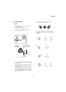
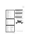
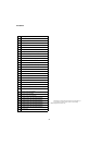
DEFLECTION SYSTEM ADJUSTMENT
1. Enter into the ‘Geometry Adjustment’ service menu.
2. Select and adjust each item in order to obtain the optimum
image.
GEOMETRY ADJUSTMENT
V size Adj
V position Adj
S Correction Adj
V Linearity Adj
H size Adj
H position Adj
Pin Amp Adj
Pin Phase Adj
AFC Bow Adj
AFC Angle Adj
EHT V 1
EHT H 0
Lo Corn Pin Adj
Up Corn Pin Adj