


24
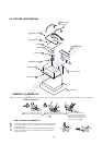
FOCUS
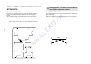
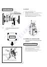
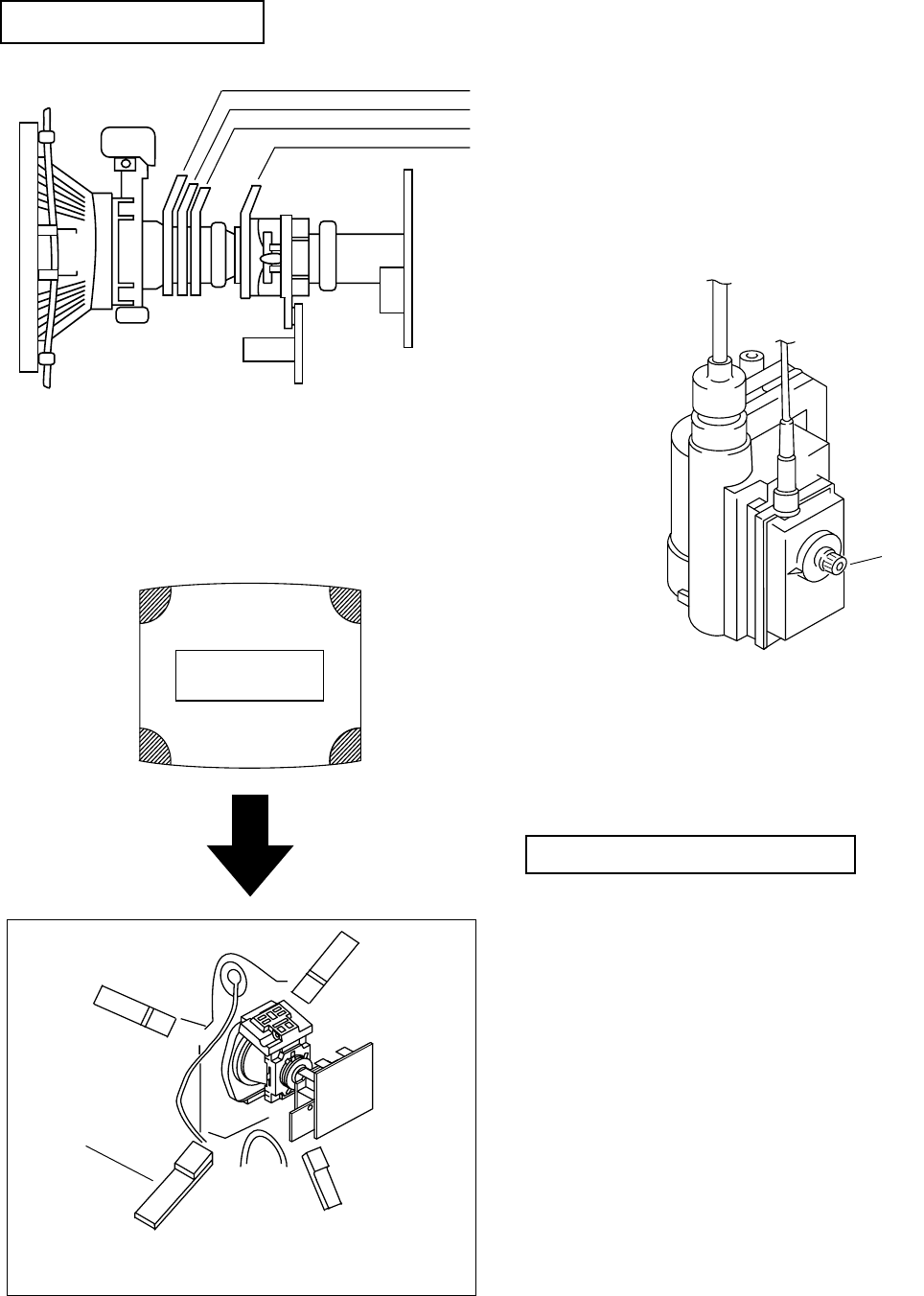
Layout of each control
Fig 3-5
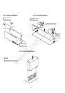
Note : If you are unable to adjust the corner convergence
properly, this can be corrected with the use of
permalloys.
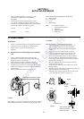
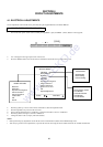
3-3. FOCUS
1. Receive a television broadcast signal.
2. Normalize the picture setting.
3. Adjust the focus control located on the flyback transformer to
obtain the best focus at the centre of the screen.
Bring only the centre area of the screen into focus, the
magenta-ring appears on the screen. In this case, adjust the
focus to optimize the screen uniformly.
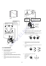
3-4. SCREEN (G2), WHITE BALANCE
[Adjustment in the service mode using the remote
commander]
G2 adjustment (RV5376)
1. Input a dot signal from the pattern generator.
2. Set the Picture, Brightness and Colour to minimum.
3. Apply 175V DC from an external power supply to the
R, G and B cathodes of the CRT.
4. Whilst watching the picture, adjust the G2 control
RV5376 [SCREEN] located on the C Board to the point
just before the flyback return lines disappear.
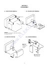
Y-splitting axis correction magnet
V STAT convergence magnet
BMC (Hexaploe) magnet
Purity magnet
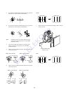
a-d: screen-corner
convergence defect
a
b
c
d
Convergence adjustment with permalloy
Permalloy Assy
X-4387-214-1
www.ELEKO.de