


DC 19.5V
AUDIO OUT
AUDIO IN
AUX1–VIDEO IN–AUX2
CAMERA UNIT MIC
(PLUG IN POWER)
ISDN UNIT WHITE
BOARD
(MIXED)
AUX
MAIN
–
MONITOR
–
SUB
VIDEO OUT
RGB OUT DSB
IR OUT
100BASE-TX
10BASE-T
12
12
AUX MIC 1 MIC 2 MIC 3 MIC 4 MIC 5 TO PROCESSOR RGB OUTOUTLINE OUT IN
TERMINAL VISCA OUT
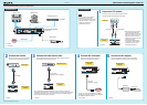
Connection Sheet (ISDN Connection)
2
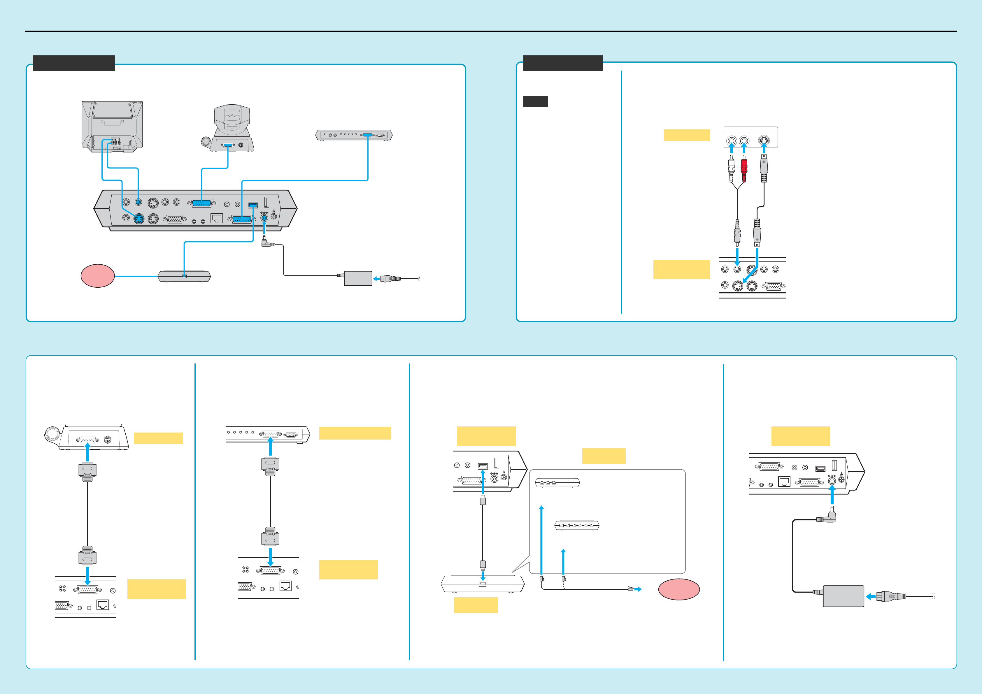
Connect the camera.
Connect the Camera Unit and
Communication Terminal using the
supplied camera cable.
4
Connect the ISDN Unit.
1 Connect the ISDN Unit and Communication Terminal using the interface cable
supplied with the ISDN Unit.
2 Connect the ISDN Unit to an ISDN line using an ISDN modular cable (not supplied).
3
Connect the Data Solution Box.
Connect the Data Solution Box and Communication
Terminal using the cable supplied with the Data Solution
Box.
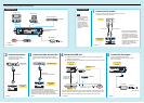
1
Connect the TV monitor.
Connect the TV monitor and Communication Terminal using the
supplied audio cable and S-video cable.
•When connecting a second monitor,
use the VIDEO OUT MONITOR SUB
or the RGB OUT connector on the
Communication Terminal, or the RGB
OUT connector on the Data Solution
Box. For details, refer to the Operating
Instructions.
• The AUDIO OUT (MIXED) jack is used
to make an audio recording of a
conference. This is not used during
regular conferences.
DC 19.5V
MIC
(PLUG IN POWER)
ISDN UNIT
WHITE
BOARD
DSB
12
123
123456
DC 19.5V
N
CAMERA UNIT MIC
(PLUG IN POWER)
ISDN UNIT
WHITE
BOARD
DSB
IR OUT
100BASE-TX
10BASE-T
12
12
5
Connect the AC adaptor.
Connect the supplied AC adaptor to the
Communication Terminal, and then plug the power
cord into a wall outlet.
AC adaptor*
to a wall outlet
(100 - 240V AC)
Power cord*
1 TV monitor**
2 Camera Unit
Communication Terminal
PCS-P1/P1P
3 Data Solution Box
5 AC adaptor
Power cord*
PCS-AC195*
PCS-C1/C1P*
4 ISDN Unit**
PCS-DSB1**
System Setup
Data Solution Box
ISDN
line
Used with the Data Solution Box for the first time, the
Communication Terminal may automatically upgrade the software
of the Data Solution Box. While the upgrading message is
displayed on the monitor screen, be sure not to turn off the
Communication Terminal. Doing so may cause malfunction of the
system.
Used with an ISDN Unit for the first time, the Communication Terminal may automatically upgrade the
software of the ISDN Unit. While the upgrading message is displayed on the monitor screen, be sure
not to turn off the Communication Terminal. Doing so may cause malfunction of the system.
AUDIO OUT
AUDIO IN
AUX1–
VIDEO IN
–AUX2
(MIXED)
AUX
MAIN
–
MONITOR
–
SUB
VIDEO OUT
RGB OUT
S-VIDEO INAUDIO IN
LR
S-video cable*Audio cable*
AUDIO IN
CAMERA UNIT
M
(PLUG
RGB OUT
IR OUT
100BASE-TX
10BASE-T
12
1
TERMINAL VISCA OUT
Camera cable*
* supplied
** not supplied
Let’s connect
•Be sure to turn off all the
equipment before making
any connections.
•Do not connect/disconnect
the camera cable or the
interface cable with the
power on. Doing so may
damage the Camera Unit,
Communication Terminal or
ISDN Unit.
* supplied
TV monitor
Communication
Terminal
Camera Unit
Communication
Terminal
* supplied
** not supplied
Communication
Terminal
Communication
Terminal
* supplied
Notes
AUDIO IN
CAMERA UNIT
M
(PLUG
RGB OUT
IR OUT
100BASE-TX
10BASE-T
12
1
MIC 1 MIC 2 MIC 3 MIC 4 MIC 5 TO PROCESSOR RGB OUT
ISDN modular cable**
PCS-B384**
PCS-B768**
1
2
to ISDN 1-3
to ISDN 1-6
ISDN Unit
(front)
to ISDN
line
Communication
Terminal
ISDN Unit
(rear)
Interface cable
(supplied with
the ISDN Unit)
Interface cable
(supplied with the PCS-DSB1)