


eclubthai eclubthai eclubthai eclubthai eclubthai
eclubthai eclubthai eclubthai eclubthai eclubthai
eclubthai eclubthai eclubthai eclubthai eclubthai
eclubthai eclubthai eclubthai eclubthai eclubthai
eclubthai eclubthai eclubthai eclubthai eclubthai
eclubthai eclubthai eclubthai eclubthai eclubthai
eclubthai eclubthai eclubthai eclubthai eclubthai
eclubthai eclubthai eclubthai eclubthai eclubthai
eclubthai eclubthai eclubthai eclubthai eclubthai
eclubthai eclubthai eclubthai eclubthai eclubthai
DVP-NS355/NS501P/NS507P/NS525P/NS575P/NS585P
4-3 4-4
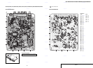
For printed wiring boards:
• : indicates a lead wire mounted on the component
side.
• : indicates a lead wire mounted on the printed side.
• a : Through hole.
•
: Pattern from the side which enables seeing.
(The other layers’ patterns are not indicated.)
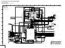
For schematic diagrams:
• All capacitors are in µF unless otherwise noted. pF : µµF.
50V or less are not indicated except for electrolytics and
tantalums.
• All resistors are in ohms, 1/4W (Chip resistors : 1/10W)
un-less otherwise specified.
kΩ = 1000Ω, MΩ = 1000kΩ.
• Caution when replacing chip parts.
New parts must be attached after removal of chip.
Be careful not to heat the minus side of tantalum capacitor,
because it is damaged by the heat.
• All variable and adjustable resistors have characteristic
curve B, unless otherwise noted.
•
: non flammable resistor.
•
: fusible resistor.
•
: panel designation.
• f : internal component.
•
: adjustment for repair.
•
: B+ Line.
•
: B– Line.
• Circled numbers refer to waveforms.
• Voltages are dc between measurement point.
• Readings are taken with a color-bar signal on DVD refer-
ence disc and when playing CD reference disc.
• Readings are taken with a digital multimeter (DC 10MΩ).
• Voltage variations may be noted due to normal production
tolerances.
Caution:
Pattern face side: Parts on the pattern face side seen
from
(Side A) the pattern face are indicated.
Parts face side: Parts on the parts face side seen from
(Side B) the parts face are indicated.
When indicating parts by reference
number, please include the board
name.
Note:
The components identi-
fied by mark or dotted
line with mark
are criti-
cal for safety.
Replace only with part
number specified.
Note:
Les composants identifiés par
une marque sont critiques
pour la sécurité.
Ne les remplacer que par une
pièce portant le numéro
spécifié.
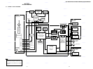
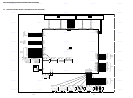
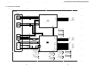
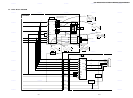
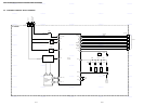
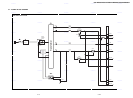
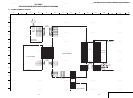
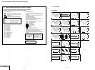
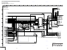
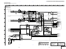
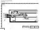
4-2. PRINTED WIRING BOARDS AND SCHEMATIC DIAGRAMS
THIS NOTE IS COMMON FOR WIRING BOARDS AND SCHEMATIC DIAGRAMS.
(In addition to this, the necessary note is printed in each block)
B+
B–
MV-044 BOARD
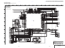
IC102 6 (CD PB)
1
1
2
3
1.4V
2
IC102 6 (DVD PB)
IC102 7 (CD PB)
IC102 7 (DVD PB)
IC102 qk (CD PLAY)
IC102 qk (DVD PLAY)
3
1.4V
IC102 wa (CD PLAY)
IC102 wa (DVD PLAY)
4
1.4V
4
1.4V
IC201
12
1Vp-p
38ns
IC201 (CD)
13
IC201 (CD)
14
1.4V
14
1.4V
186
203
IC201 (DVD)
13
203
205
IC201 (DVD)
205
IC102 oh (CD PB)
5
200nsec
IC102 oh (DVD PLAY)
5
1.1Vp-p
100nsec
IC201 (DVD PLAY)
IC201 (CD PLAY)
15
50ns/div
15
200ns/div
IC201 C/BAR PB
8
1V
63.5usec
IC201 C/BAR PB
9
1Vp-p
63.5usec
IC201
10
0.6Vp-p
63.5usec
IC201
11
0.6Vp-p
63.5usec
0.8Vp-p
215 216
215
172
173
170
168
166
164
216
IC201 C/BAR PB
7
1Vp-p
63.5usec
IC201 C/BAR PB
6
0.7Vp-p
63.5us
0.8Vp-p
0.8Vp-p
1.4V
1.4V
0.8Vp-p
50ns/div
0.8Vp-p
50ns/div
0.8Vp-p
200ns/div
0.8Vp-p
200ns/div
3.3Vp-p
40.71ns
IC207 1 (DVD)
17
3.3Vp-p
44.24ns
IC207 1 (CD)
16
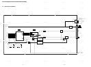
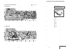
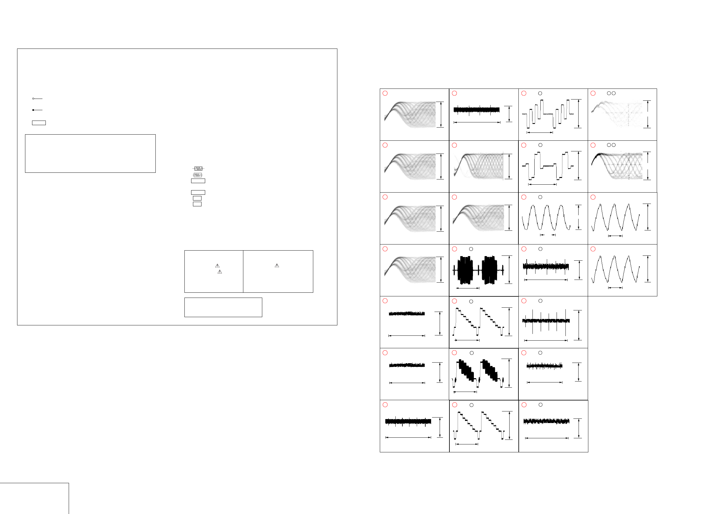
4-3. WAVEFORM
WAVEFORM
MV-044
• Abbreviation
CA2 : Canada model
PX3 : PX model
MX2 : Mexico model
E32 : Latin model
BR4 : Brazil model
HK2 : Hong Kong model
SP6 : GA model
TW1 : Taiwan model
KR2 : Korea model
EA4 : Saudi Arabia model
ME2 : Middle East model
ME5 : India model
AU2 : Australia model
CN6 : China model
AR2 : Argentina model
U2 : US model
IR2 : Iran model