


– 7 –
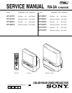
KP-43T75/48S75/
53N77/53S75/61S75
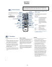
RM-Y906
TABLE OF CONTENTS
Section Title Page
–––––– –––– ––––
Section Title Page
–––––– –––– ––––
SELF DIAGNOSIS FUNCTION............................................ 4
1. GENERAL
Remote Control ....................................................................... 9
Precautions .............................................................................. 9
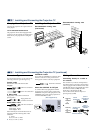
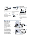
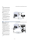
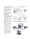
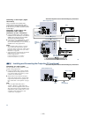
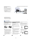
Installing and Connecting the Projection TV........................ 10
Basic Set Up.......................................................................... 15
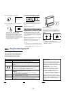
Using Your New Projection TV ............................................ 16
Adjusting Your SET UP (menus) .......................................... 19
Operating Video Equipment.................................................. 30
Operating a Cable Box or Satellite Receiver (SAT).............. 31
Troubleshooting .................................................................... 31
2. DISASSEMBLY
2-1. Rear Board Removal ................................................. 33
2-2. Chassis Assy Removal .............................................. 33
2-3. Service Position......................................................... 33
2-4. HA Board and HB Board Removal
(Except KP-43T75) ................................................... 33
2-5. HA Board and HB Board Removal(KP-43T75) ....... 34
2-6. Mirror Cover Removal .............................................. 34
2-7. Beznet Assy Removal................................................ 34
2-8. HC Board and S Board Removal .............................. 34
2-9. A Board and G Board Removal ................................ 35
2-10. Picture Tube Removal ............................................... 35
2-11. High-Voltage Cable Installation and Removal.......... 35
3. SET-UP ADJUSTMENTS
3-1. Screen Voltage Adjustment (Coarse Adjustment) ..... 36
3-2. Screen (G2) Adjustment (Fine Adjustment).............. 36
3-3. Deflection York Tilt Adjustment ............................... 36
3-4. Focus Lens Adjustment ............................................. 36
3-5. Focus VR Adjustment ............................................... 37
3-6. 2-Pole Magnet Adjustment (Green, Red).................. 37
3-7. 4-Pole Magnet Adjustment........................................ 37
3-8. Defocus Adjustment (Blue) ....................................... 37
3-9. Electrical Adjustment by Remote Commander......... 38
3-10. Registration Adjustment (PJE) .................................. 43
3-11. Auto Registration Error Code List ........................... 46
4. SAFETY RELATED ADJUSTMENTS
4-1. HV Regulation Circuit Check and Adjustment ......... 47
4-2. HV Hold Down Circuit Operation and Adjustment .. 47
4-3. +B Max Voltage Confirmation .................................. 47
4-4. +B OVP Confirmation............................................... 48
5. CIRCUIT ADJUSTMENTS
5-1. TV Input Sub Contrast Adjustment
(VPNT-SCON) .......................................................... 49
5-2. Video Input Sub-HUE and Sub-Color Adjustment
(VPNT-SHUE, SCOL) .............................................. 49
5-3. Component Input Sub-HUE and SubColorAdjustment
(DAC-UVSH, UVSC) ............................................... 49
5-4. P & P Sub Contrast Adjustment (SC-SYDR) ........... 49
5-5. Sub-HUE, Sub-Color and Main Contrast Adjustment
(MC-MYDR, MSHU, MSCL, SC-SSHU, SSCL) .... 50
5-6. Bar Display Position Adjustment (OP-DISP) ........... 50
5-7. PIP Position Adjustment (PI-PIPH, PIPV)................ 50
6. DIAGRAMS
6-1. Block Diagram (1)..................................................... 51
Block Diagram (2)..................................................... 53
Block Diagram (3)..................................................... 59
Block Diagram (4)..................................................... 63
Block Diagram (5)..................................................... 65
6-2. Frame Schematic Diagram ........................................ 67
6-3. Circuit Boards Location ............................................ 70
6-4. Printed Wiring Boards and Schematic Diagrams ...... 70
• A (1/3)Board ........................................................... 71
• A (2/3)Board ........................................................... 75
• A (3/3)Board ........................................................... 79
• G Board................................................................... 87
• CG Board ................................................................ 94
• CR Board ................................................................ 95
• CB Board ................................................................ 95
• HA Board ................................................................ 97
• HC Board ................................................................ 97
• HB Board ................................................................ 98
6-5. Semiconductors ......................................................... 99
7. EXPLODED VIEWS
7-1. Cover (KP-43T75)................................................... 101
7-2. Cover (KP-48S75) ................................................... 102
7-3. Cover (KP-53N77/53S75/61S75) ........................... 103
7-4. Chassis (KP-43T75) ................................................ 104
7-5. Chassis (Except KP-43T75) .................................... 105
7-6. Picture Tube ............................................................ 106
8. ELECTRICAL PARTS LIST ................................. 107