– 12 –
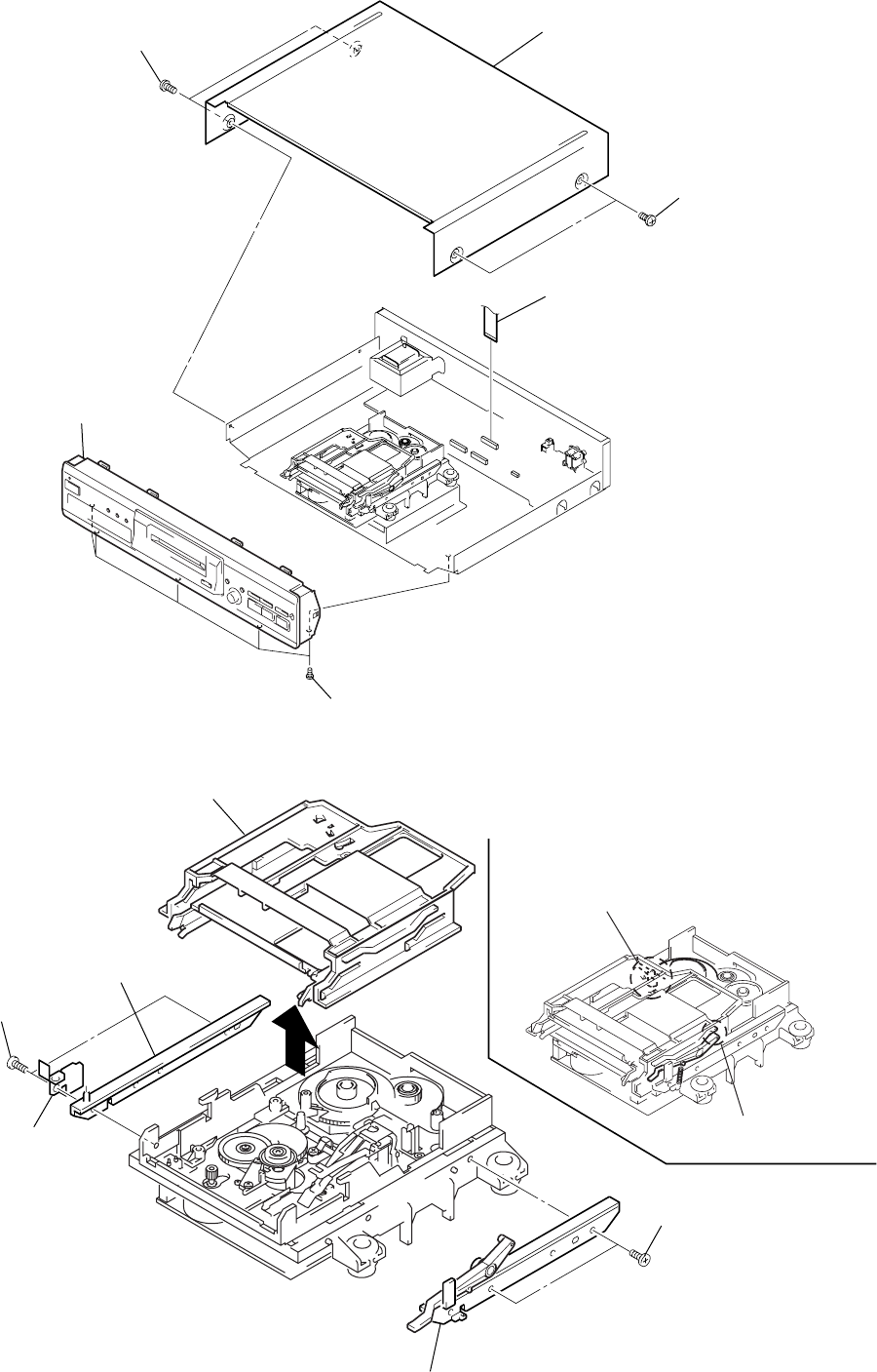
• Note for Installation of Slider (Cam)
SECTION 3
DISASSEMBLY
Note: Follow the disassembly procedure in the numerical order given.
3-1. CASE AND FRONT PANEL
3-2. SLIDER (CAM)
1
Two screws (Case)
4
Flat type wire (CN421)
5
Five screws (BVTP3x8)
6
Front panel assembly
2
Two screws (Case)
3
Case
1
Two screws (BTP2.6x6)
2
Bracket (Guide L)
3
Leaf spring
5
Bracket (Guide R)
6
Slider (Cam)
4
Two screws (BTP2.6x6)
Set the shaft of Lever (O/C) to
be at the position in the figure.
Set the shaft of Cam gear to
be at the position in the figure.


