


Quick Start Guide Speco Technologies DVR-4TH/8TH/16TH
Customer Service: 1-800-645-5516 x196
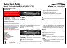
The jog/ shuttle knob, shown in the figure below, is a combination
of a shuttle ring with an embedded jog disk, which is used to
provide wide range in playback control. Note that the jog/ shuttle
knob is active only when the DVR unit is in Playback mode.
While playing back video, you can use the shuttle ring to select
different speeds of forward and backward playing. Rotating the
shuttle ring causes the unit to playback in fast forward/ backward
playing speed. According to the angle you rotate the shuttle ring,
you can choose the playing speed from 1×, 2×, 4×, 8×, 16×, and
32×, in both forward and reverse directions, shown in the figure
below:
Inside the shuttle ring is the jog disk, shown in the illustration
below, it can be turned completely in either direction. Once you
freeze the video, you can use the jog disk to go to single-step
play back. Clockwise rotation causes forward one-step playback;
and counterclockwise rotation causes backward one-step
playback. This is for JPEG recoding only.
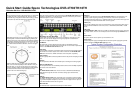
Rear Panel Connections
There are several connectors on the rear panel of the DVR-4TH/ 8TH/ 16TH series unit
available for installations. The following figure shows the connectors by name and a
detailed description of each connector follows.
Main Monitor (S-Video/ BNC/ VGA)
S-Video, BNC, and VGA output connectors are available for connecting to a main
monitor. The main monitor displays live image and playback recorded video in
full-screen or multiple window format.
Call Monitor
The call monitor is used to display full screen video of all installed cameras in
sequence. The BNC call monitor connector allows the user to connect an optional call
monitor to the DVR-4TH/ 8TH/ 16TH series unit.
Video Input
A group of BNC connectors is provided for video input streams from installed cameras.
The number of connectors equals to the number of channels. The DVR-4TH/ 8TH/
16TH series unit has 4/ 8/ 16 BNC connectors on the rear panel, respectively.
Video Looping
The other group of BNC connectors positioned on the rear panel is for looping out video
input.
RS-232C
The unit provides a RS-232C communication port for sending and receiving signals.
Alarm I/O & RS-485 Port
The unit provides Alarm I/O and RS-485 ports that offer users the flexibility required to
connect the unit to other devices.
NAS
The DVR-4TH/ 8TH/ 16TH series unit can connect to a Network Attached Storage
(NAS) device through this connector to increase storage space and allow vast
recording.
Audio In
The DVR-4TH/ 8TH/ 16TH series unit provides 4/ 8/ 16 channels of audio recording
accordingly. The Audio In connectors are offered for connecting audio source devices
(e.g. external amplified microphone) to the unit. The PIN of upper row is for input of
each channel while the lower row is for ground.
Main Audio Out
One RCA connector is provided for audio output of main monitor.
Audio Out
In addition to the RCA connector, the DVR-4TH/ 8TH/ 16TH series unit provides 4/ 8/ 16
channels of audio exporting accordingly. The Audio Out connectors are provided for
connecting audio output devices (e.g. amplified speakers) to the unit. The PIN of upper row
is for output of each channel while the lower row is for ground.
USB 2.0 (x4)
There are two USB 2.0 ports on the rear panel and two on the front panel to allow users to
connect external USB devices to the unit, such as a ThumbDrive®, DVD+RW, or a USB
mouse.
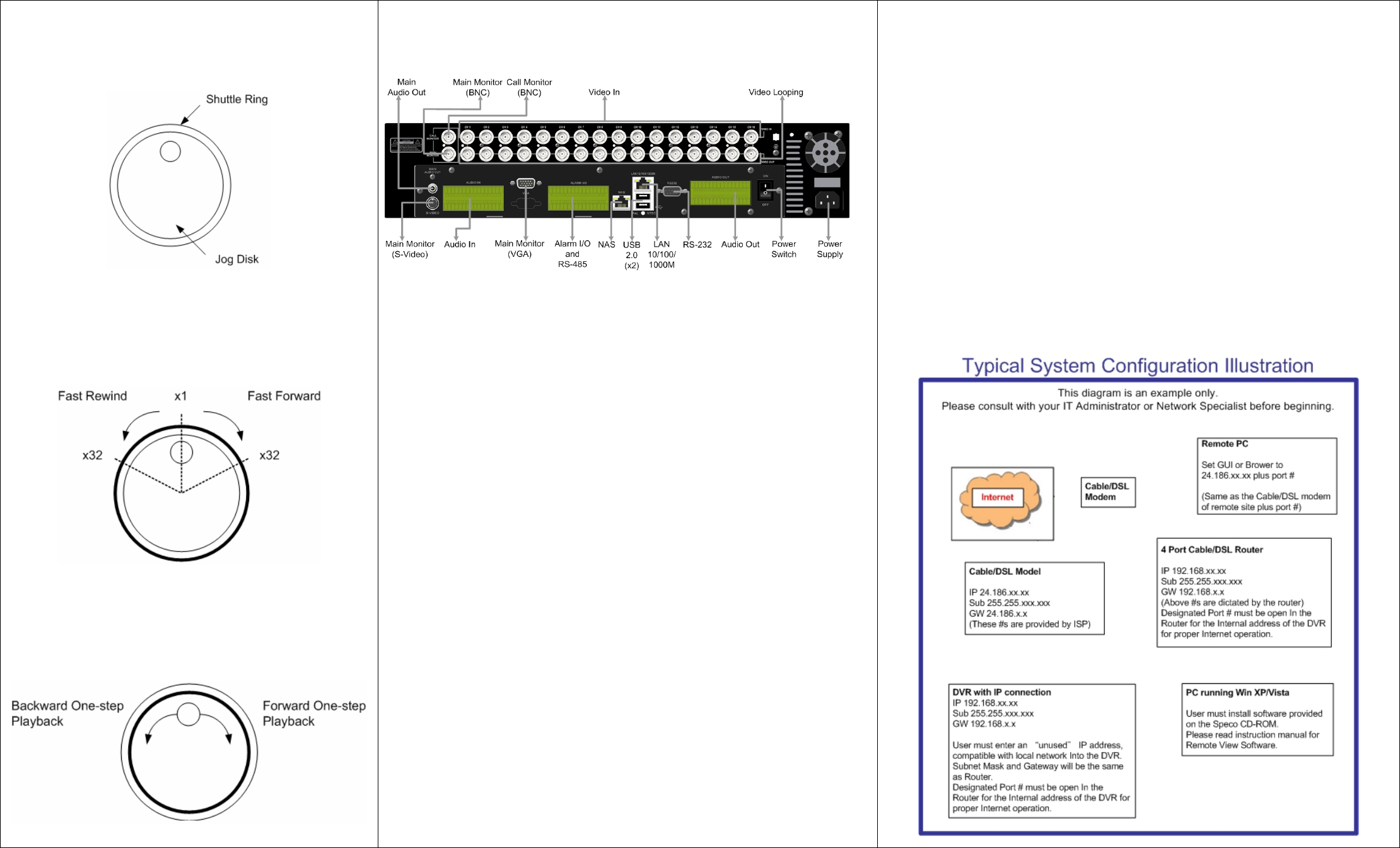
LAN (RJ45)
The DVR-4TH/ 8TH/ 16TH series unit is capable of networking. Once the unit is connected
to the LAN network, the users can remotely access the unit through SpecoRemote™ on a
PC.
Power Switch
The power switch is used to power up or shut down the unit.
Power Supply
Connect the power supply cord shipped with the unit to the power supply jack to provide
power to operate the DVR-4TH/ 8TH/ 16TH series unit.