


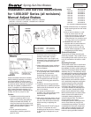

Installation and Service Instructions
for 1-056-X00* Series (all revisions)
Manual Adjust Brakes
®
Spring-Set Disc Brakes
P/N 8-078-905-60
effective 03/16/06
Typical Nameplate
Important
Please read these instructions carefully
before installing, operating, or servicing
your Stearns Brake. Failure to comply
with these instructions could cause injury
to personnel and/or damage to property if
the brake is installed or operated incor-
rectly. For definition of limited warranty/lia-
bility, contact Rexnord Industries, LLC,
Stearns Division,5150 S. International Dr.,
Cudahy, WI 53110, (414) 272-1100.
Caution
1. Installation and servicing must be
made in compliance with all local
safety codes including Occupational
Safety and Health Act (OSHA). All
wiring and electrical connections must
comply with the National Electric Code
(NEC) and local electric codes in
effect.
2. Do not operate the brake in
atmospheres containing explosive
gases or dusts.
3. To prevent an electrical hazard,
disconnect power source before
working on the brake. If power
disconnect point is out of sight, lock
disconnect in the off position and tag
to prevent accidental application of
power.
4. Make certain power source conforms
to the requirements specified on the
brake nameplate.
5. Be careful when touching the exterior
of an operating brake. Allow sufficient
time for brake to cool before
disassembly. Surfaces may be hot
enough to be painful or cause injury.
6. Do not operate brake with housing
removed. All moving parts should be
guarded.
7. Installation and servicing should be
performed only by qualified personnel
familiar with the construction and oper-
ation of the brake.
8. For proper performance and
operation, only genuine Stearns parts
should be used for repairs and
replacements.
9. After usage, the brake interior will con-
tain burnt and degraded friction mate-
rial dust. This dust must be removed
before servicing or adjusting the
brake.
DO NOT BLOW OFF DUST using an
air hose. It is important to avoid
dispersing dust into the air or inhaling
it, as this may be dangerous to your
health.
a) Wear a filtered mask or a respirator
while removing dust from the inside
of a brake.
b) Use a vacuum cleaner or a soft
brush to remove dust from the
brake. When brushing, avoid caus-
ing the dust to become airborne.
Collect the dust in a container, such
as a bag, which can be sealed off.
10. Caution! While the brake is
equipped with a manual release to
allow manual shaft rotation, the
motor should not be run with the
manual release engaged, to avoid
overheating the friction disc(s).
General Description
These series of brakes are spring-set,
electrically released. They contain one or
more rotating friction discs (4) driven by a
hub (16) mounted on the motor or other
shaft.
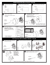
Operating Principle
These series contain one or more friction
discs (4) assembled alternately between
the endplate (2) friction surface, stationary
disc(s) (3) and pressure plate (also called
stationary disc) (3). The stationary disc(s)
are restrained from rotating by being keyed
into the endplate. With the brake released,
all disc pack components are free to slide
axially and the friction disc(s) to rotate.
Brake release occurs when the solenoid
coil is electrically energized, causing the
solenoid plunger to travel a specified
distance and through a lever system,
overcoming the pressure spring force.
This action releases the clamping force
on the disc pack, thereby allowing the
friction disc(s) and brake hub to rotate.
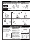
Brake sets and torque is produced when
electric current to the solenoid coil is
interrupted, thereby collapsing the
solenoid magnetic field. The solenoid
plunger returns to its original
de-energized position allowing the lever
arm to move forward by virtue of the
compressed torque springs. This action
compresses the disc pack components
which applies a retarding torque to the
brake hub and ultimately restores the
brake to a spring-set static condition.
Tools required for installation and servicing:
3/8” hex wrench 5/16” nut driver
5/16” hex wrench 1/4” screwdriver
3/16” hex wrench 8” adjustable wrench
*
This sheet includes Series 1-056,000; 1-056,100; 1-056,200;
1-056,300; 1-056,400; 1-056,500; 1-056,600 and 1-056,900.
For other series consult factory.
1-056-100
1-056-600
1-056-200
1-056-900
1-056-300
1-056-000
1-056-400
1-056-500
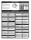
For replacement parts refer to sheets:
Series Sheet Part No.
1-056-000 8-078-906-00
1-056-100 8-078-906-01
1-056-200 8-078-906-02
1-056-300 8-078-906-03
1-056-400 8-078-906-04
1-056-500 8-078-906-05
1-056-600 8-078-906-06
1-056-900 8-078-906-09
Also available at www.rexnord.com