


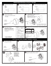

Lift plunger/solenoid
lever assembly
out of coil.
Remove plunger guide.
A) Re-insert plunger into coil; drop
pivot pin into cradle of support plate.
B) Remove screwdriver.
A) Insert new coil. (Lead wires
in same position as old coil.)
B) Insert plunger guide.
Insert screwdriver between support
plate and lever arm and pry forward.
A
B
A
B
Remove housing and disconnect power and wiring to coil.
Discard coil.
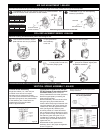
Vertical Brake Assembly
Single disc brakes (1.5, 3 & 6 lb-ft) are
universal mount and do not require
separator springs. Double disc brakes
(10-15 lb-ft.) are universal mount but require
separator springs which are preassembled
to the stationary disc. These discs are
inserted spring first into the brake.
Refer to figure 5A below.
Installation Procedure for 20 and
25 lb-ft brakes if mounted vertical
to motor shaft (These brakes are
factory assembled for horizontal operation.)
Remove support plate by loosening the
three mounting screws.
Remove stationary discs and friction discs.
Using the spring kit provided with this
brake, insert three springs of identical color
into each stationary disc hole. Springs are
inserted from the side opposite the indent
mark (see Figure 5B). Stationary disc
should be placed on a clean flat surface
with a clearance hole to allow the tip of the
spring to extend through the bottom side of
the stationary plate. Using the 1/8” pin
provided and a hammer, drive the spring
until the large coil diameter bottoms out
against the disc.
Reassemble the disc pack with the
stationary discs in the proper arrangement
shown in Figure 5C.
Mount support plate and torque screws
evenly to 55 lb-in.
Reconnect coil and replace housing per installation instructions, page 2.
3
COIL REPLACEMENT SERIES 1-056-X00
To decrease air gap, turn both adjusting
screws (10) clockwise.
As friction disc wear the air gap will increase. When plunger gets to the reset position, the air gap must be adjusted.
3/16 hex wrench
counter-clockwise
3/16 hex wrench
clockwise
AIR GAP ADJUSTMENT 1-056-X00
VERTICAL SPRING ASSEMBLY 1-056-X00
Figure 5B
Figure 5C
Figure 5A
To increase air gap, turn both adjusting screws (10) counterclockwise. Use
3/16 hex wrench, or flat screwdriver on older models.
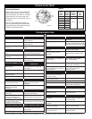
Torque
Disc
Torque
1 1.5, 3 & 6
2 10 & 15
3 20 & 25
Min/Max
.38” ± .69”
.45” ± .69”
.50” ± .69”
56,X00 Series Air Gap* (REV A & B)
*±.30”
Disc
Torque
2
3, 6,
10 & 15
3 20 & 25
Min/Max
.45” ± .69”
.50” ± .69”
56,X00 Series Air Gap* (REV C)
*±.30”
Maximum gap should never exceed .69”