Page 34
Care of SunBriteTV
Important Information About the Anti-Re ective Window on your SunBriteTV
Outdoor Television
The anti-re ective window on your all-weather TV is designed to dramatically reduce re ection and improve the contrast of
the image on your TV. In order to preserve the anti-re ective properties of the window, it is imperative that you follow the
maintenance guidelines below:
1. Clean the window by using the following directions:
To clean the SunBriteTV window, use glass cleaner and a lint-free or micro- ber cloth. Spray the solution on the cloth and
then apply to the window. DO NOT use acrylic cleaners.
2. When the TV is not in use, keep it covered with the SunBriteTV Outdoor Dust Cover
The tted dust cover is constructed with weatherproof 4-ply polypropylene UV protection fabric that protects the window
from direct and indirect sunlight, and keeps wind-blown objects from scratching the surface of the window.
To order the Dust Cover, contact your Authorized SunBriteTV dealer or SunBriteTV’s Customer Service at 866.357.8688.
General Cleaning
Remove any dirt and salt deposits from the unit, being careful to rinse the cloth frequently to avoid scratching the TV or screen
surface. Avoid using harsh chemicals, abrasives, or solvents when cleaning any surface on the unit.
Snow and Ice
Use a soft brush and towel to remove snow and ice from the unit.
Fiber Filter
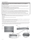
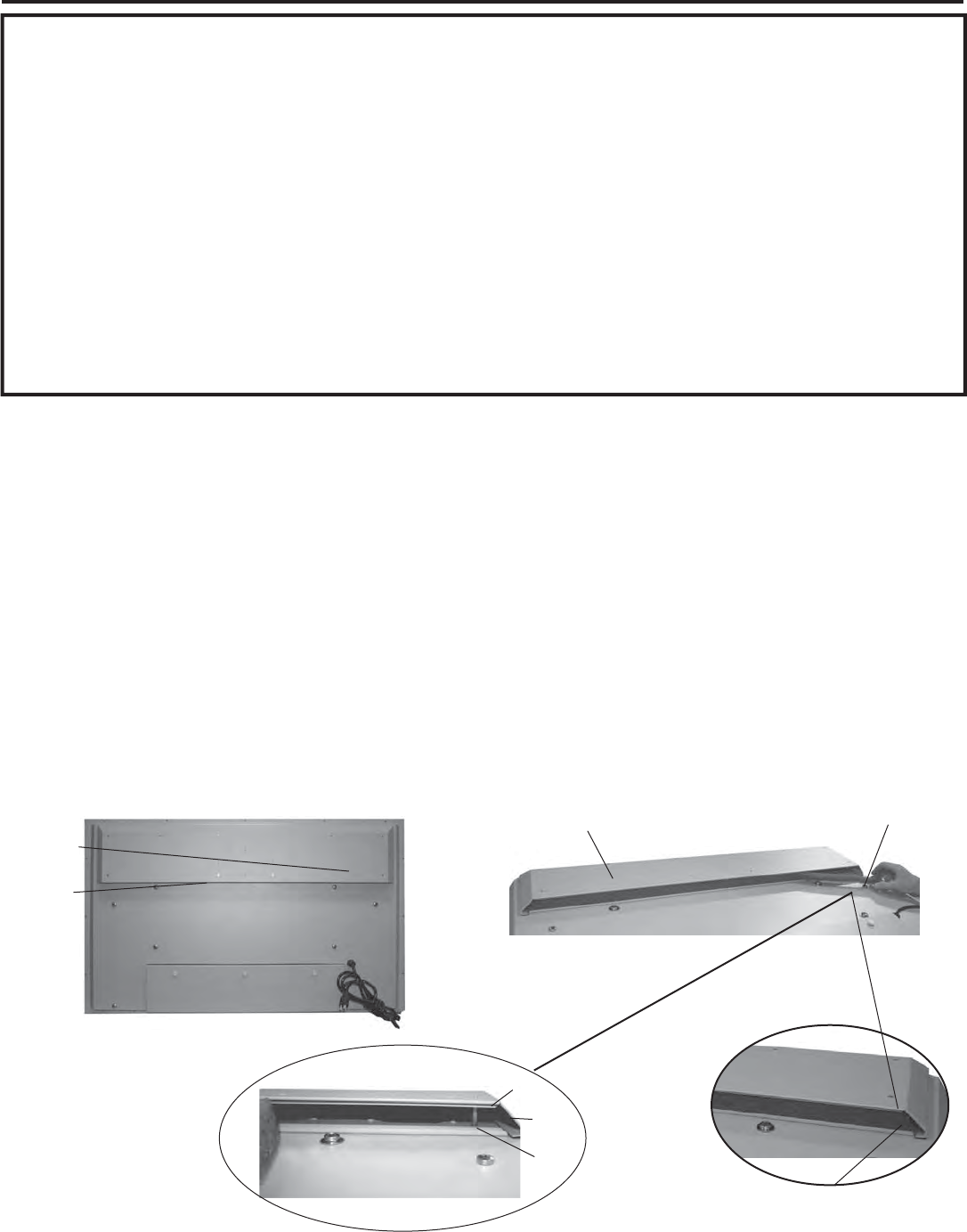
The Fiber Filter is located on the back of the unit, inside the Intake Vent at the top of the TV (Figure 1). In areas where dust or salt air
is prevalent, it is recommended that the Fiber Filter be cleaned regularly.
1. Release the Fiber Filter by pulling it out from the corner of the Intake Vent (Figure 2). Notice how the Fiber Filter ts in the upper
and lower channels, and tightly against the angled corners (Figure 3).
2. Pull the Fiber lter out of the TV, and wash it with mild detergent and warm water. After rinsing, let the Fiber Filter dry completely.
3. Put the Fiber Filter back up into the Intake Vent pushing the lter rst into the upper channel, then t it into the lower channel.
Make sure lter ts tightly against angled corners at each end of the Intake Vent. (Figure 4).
Figure 1
Figure 3
Fiber Filter
Intake Vent
Fiber Filter
Intake Vent
Figure 2
Lower Channel
Upper Channel
Angled Corner
Angled Corner
Figure 4


