Model 200AU-NOy Option Manual Addendum
5.6 Leak Check Procedure
If a leak checker is not available, it is possible to leak check the instrument using the M501Y's
pump plus a shut-off valve.
1. Turn off instrument power and pump power.
2. Cap the sample inlet port, ozone generator air inlet, and zero air inlet (if Z/S valve option
present).
3. Insert a shut-off valve between the sample pump and the vacuum manifold at the rear of
the instrument.
4. Turn on the sample pump and set the TEST function to RCEL, which measures the
reaction cell pressure. Close the shutoff valve and monitor the cell pressure. The
pressure should not drop more than 1"Hg(.5psi) in 5 minutes. If there is a leak, it is not
possible by this method to tell where it is located. You can locate the leak by using a
pressure leak checker described below.
If you have a leak checker:
1. Turn off instrument power and pump power.
2. Disconnect pump at rear panel. Cap the sample inlet port, ozone generator air inlet, and
zero air inlet (if Z/S valve option present) and connect the leak checker to the exhaust
port.
CAUTION: PRESSURE MUST BE LESS THAN 15 PSI.
3. Pressurize system and check for leaks by watching overall pressure. The pressure should
not drop more than 1"Hg (.5psi) in 5 minutes.
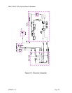
If the instrument fails the pressure test, each fitting needs to be leak checked to find the location.
Be careful that the system is always pressurized so as not to draw soap solution into the
plumbing system. Make sure you dry off any accumulated bubble solution.
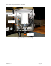
The Sensor module can be leak checked as a unit using a 1/8" tubing fitting on top of the
assembly. The same rules as above apply.
02808 Rev. E Page 30


