


3-5
Trace Oxygen Analyzer Installation 3
Teledyne Analytical Instruments
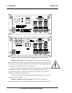
fuse receptacle, to the right of the power terminal strip, holds a 0.5 A, very
quick acting fuse. (See Fuse Replacement in chapter 5, Maintenance.)
The Power switch is located below the fuse receptacle.
WARNING: INSERT THE STRIPPED TIPS OF WIRES ENTIRELY
INTO THE TERMINAL BLOCKS. DO NOT LEAVE
EXPOSED WIRE OUTSIDE OF THE HOLES IN THE
BLOCKS.
CAUTION: The control unit chassis must be isolated from the
grounding system of the DC input power.
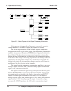
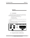
Analog Outputs: There are three DC output signal connectors with
screw terminals on the panel. There are two wires per output with the polar-
ity noted. See Figure 3-3. The outputs are:
0–10 V concentration: Voltage rises with increasing oxygen concentra-
tion, from 0 V at 0 oxygen content to 10 V at full
scale oxygen content. (Full scale = 100 % of
programmed range.)
0–10 V Range ID: 03.33 V = Low Range, 06.66 V = High Range,
10 V = Air Cal Range.
4–20 mA concentration: Current increases with increasing oxygen concen-
tration, from 4 mA at 0 oxygen content to 20 mA
at full scale oxygen content. (Full scale = 100 %
of programmed range.)
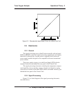
Alarm Relays: The three alarm-circuit connectors are screw terminals
for making connections to internal alarm relay contacts. There is one set of
contacts for each type of alarm. Contacts are Form C, with normally open
and normally closed contact connections capable of switching up to 0.5
ampere at 125 V ac into a resistive load.
The alarm relay circuits are designed for failsafe operation, meaning the
relays are energized during normal operation. If power fails the relays de-
energize (alarms activated).
The contact connections are indicated diagrammatically on the rear
panel as Normally Closed, Common, and Normally Open. Figure 3-2
explains how these act in failsafe operation.