


Model GFC7000T Carbon Dioxide Analyzer
Teledyne Analytical Instruments 5
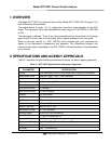
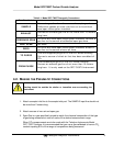
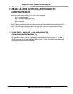
Table 4-1. Model GFC 7000T Pneumatic Connections
Rear Panel Label Function
SAMPLE
Connect a gas line from the source of sample gas here.
Calibration gasses are also inlet here on units without
zero/span valve option installed.
EXHAUST
Connect an exhaust gas line of not more than 10 meters
long here.
PRESSURE SPAN
On units with zero/span valve option installed, connect a
gas line to the source of calibrated span gas here.
VENT SPAN Not used
ZERO
On units with zero/span valve option installed, attach a
gas line to the source of zero air here.
TO PURGE
This inlet supplies purge air to the GFC wheel housing
Connect a source of dried air that has been scrubbed of
CO
2
.
FROM PURGE
This exhausts purge air to the GFC wheel housing.
Connect an exhaust gas line of not more than 10 meters
long here. It is only used on the GFC 7000TU instrument.
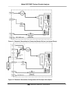
4.2. MAKING THE PNEUMATIC CONNECTIONS
CAUTION
Venting should be outside the shelter or immediate area surrounding the
instrument.
1. Attach a sample inlet line to the sample inlet port. The SAMPLE input line should not
be more than 2 meters long.
2. Attach sources of zero air and span gas
3. Span Gas is a gas specifically mixed to match the chemical composition of the type
of gas being measured at near full scale of the desired measurement range.
When CO
2
measurements are to be made with the Teledyne Instruments Model
GFC 7000T Analyzer it is recommended that you use a gas calibrated to have a CO
2
content equaling 80% of the range of compositions being measured.