Antenna Placement for Optimum Range
and Rack Mounting
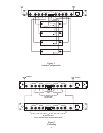
For maximum range and when rack mounting,
the antennas must be remotely located.
The ALP-450 comes complete with a variety of
mounting hardware and 10 feet (3 meters) of
low loss coaxial cable. A combination mounting
bracket (Model No. AB-2) with 10 feet of coax
-
ial cable is available for 1/2 wave antennas.
Antennas should be placed in a location with a
clear “signal path” to the transmitter. This “path”
should be as short and free of obstructions as
possible. Obstructions, such as walls ceilings,
and metal objects, will reduce range and perfor
-
mance.
Rack Mounting
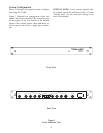
Insert the unit into a 19" rack enclosure and se
-
cure with screws (not supplied).
Rack Mounted Antenna Connectors
Antenna cable connections may be made to the
front of the rack mounted UAD4 by installing
the adaptor cables supplied. Proceed as follows:
·
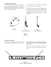
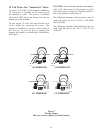
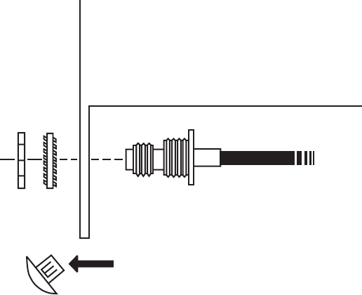
Remove the plug “knock outs” from the
front panel. See Figure 6.
·
Install the adaptor cables from the back side
of the bracket.
·
Tighten the nut and lockwasher securely.
·
Attach the other end of the cables to the in
-
puts of the UAD4. Tighten securely.
Front of rack antenna connectors were de
-
signed to allow easier hook up of antenna ca
-
bles. We do not recommend mounting
antennas directly to the connectors since per
-
formance may be degraded.
Coax Cable
For best results, it is recommended that cable
losses be kept under 4 dB. (Every 3 dB of signal
loss results in a system operating distance reduc-
tion of 25%.
See the accessories section of this manual for
special low loss cable assemblies.
-5-
REMOVE PLUG
Figure 6
Antenna Connectors


