9
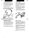
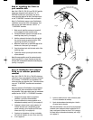
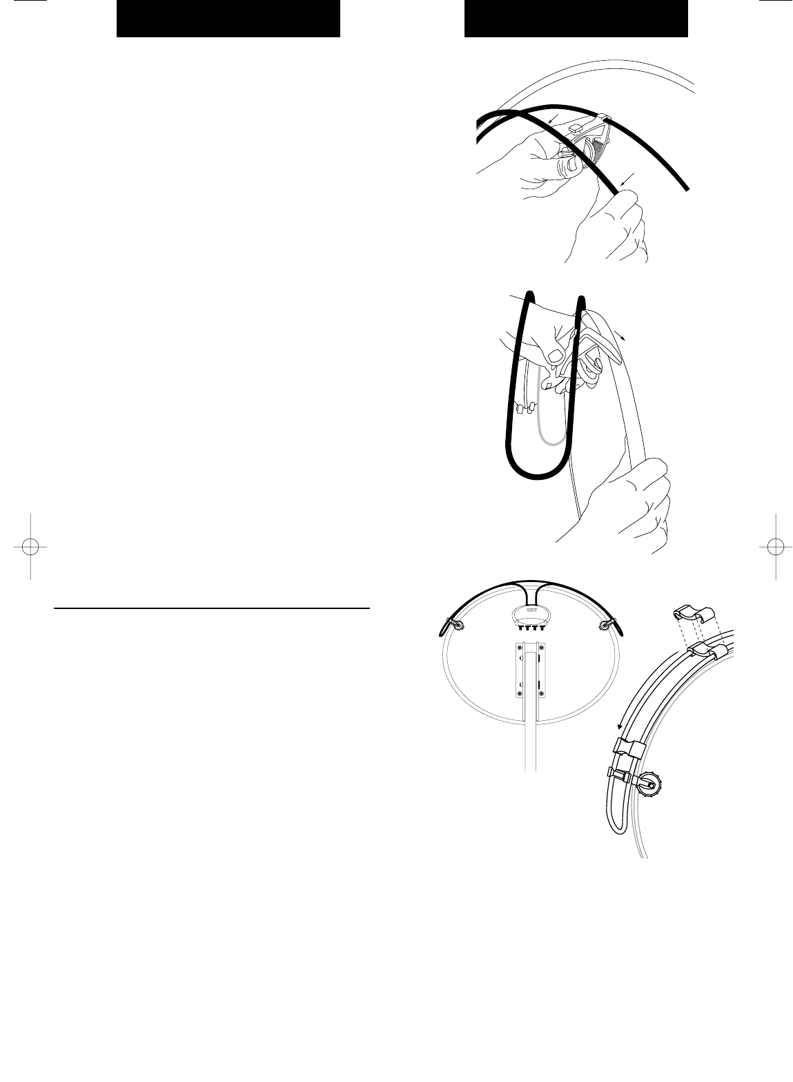
Fig 3
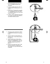
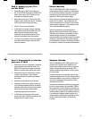
Fig 5
5. Aprete la antena otra vez sobre la muesca poste-
rior en la abrazadera de montaje.
6. Ajuste las abrazaderas haciendo girar el tornillo
de mano hacia la derecha.
Nota: Recomendamos el uso de las clips de seguridad
proveidas, para cuaalquier reflector parabólico de 20
pulg o mas grande. Aprete las clips al TV44 y empuje-
las abajo hacia la abrazadera de montaje (vea la Fig 5
en la pagina 9).
Step A: Installing the TV44 on
your satellite dish
Note: Terk’s TRK-S23, TRK-S24, and TRK-S25 satellite
dishes have integrated multi-switches. The “TO
RECEIVER”terminals are connected to the cables
coming from the bottom of the dish. Treat these cables
as the “TO RECEIVER” terminals of the multi-switch.
Note: For Dish Network owners; some Dish Network
installations use smaller SW21 multi-switches. Treat
these as one multi-switch with two “OUTPUT” or
“TO RECEIVER” terminals.
1. Make sure all satellite receivers are turned off
and unplugged from the electrical outlet.
2. Unsnap the antenna from the back notch of the
mounting clamp (see Fig 3 on page 9).
3. Hold the antenna to the back of the dish so that
the circular housing is centered with the TERK
logo facing out (see Fig 5 on page 9).
4. Maneuver clamps over or around the edge of the
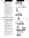
dish one at a time (see Fig 4 on page 9).
5. Snap the antenna back into the back notch of the
mounting clamp.
6. Tighten the clamps by turning the thumb-wheel
screw clockwise.
Note: We recommend the use of the enclosed security
clips for any dish 20” or larger. Snap the security clips
onto the TV44 and slide down towards the mounting clips
(see Fig 5 on page 9).
8
Paso A: Instalación de la antena
TV44 en su reflector parabólico
satelital
Nota: Terk’s TRK-S23, TRK-S24, y TRK-S25 reflectores
parabólicos tienen conmnutadores múltiples integrados.
Los terminales “TO RECEIVER” son conectados a los
cables que salen por abajo del plato. Trate estos cables
como los “TO RECEIVER” terminales del conmutador
múltiple.
Nota: Para usadores de Dish Network; unas instalaciónes
de Dish Network usan conmutadores múltiple SW21
mas pequeños. Trate estos cables como un conmutador
multiple con dos “OUTPUT” o “TO RECEIVER” terminales.
1. Asegúrese de apagar todos los receptores
satelitales y que esten desenchuflados.
2. Separe la antena de la muesca posterior en la
abrazadera de montaje (vea la Fig 3 en la pagina 9).
3. Sostenga la antena hacia la parte posterior del
reflector de modo que el alojamiento circular
quede centrado y con el logotipo de TERK hacia
afuera (vea la Fig 5 en la pagina 9).
4. Desplace las abrazaderas a lo largo o alrededor
del borde del reflector, de una a la vez (vea la Fig
4 en la pagina 9).
Fig 4


