


1.3SystemRequirements
1.4ElectrostaticDischargeWarning
1.5FunctionControlforDAIInterfaceFormat
1.6ResetOperation
www.ti.com
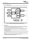
SystemRequirements
TheDEM-DSD1796/PCM1795/PCM1796/PCM1798EVMhasthefollowingrequirements:
•±15-VanalogpowersupplyatAVCC+,AVCC–,andGND
•5-VDACpowersupplyatVCCandGND
•S/PDIFinput(samplingratef
S
isupto96kHz)connectedatthecoaxialoropticalconnector
•RCAanalogoutputconnectedatCN103(Lch)andCN104(Rch);analogfull-scaleoutputlevelis4.5
V
RMS
.
•PCconnectedtoprinterconnectorCN003fordemonstrationsoftwareoperation(ifnecessary)
•Appropriatetestmodule:
–DEM-PCM1795:forPCM1795
–DEM-PCM1796:forPCM1796
–DEM-DSD1796:forDSD1796
–DEM-PCM1798:forPCM1798
ManyofthecomponentsontheDEM-DSD1796/PCM1795/PCM1796/PCM1798EVMaresusceptibleto
damagebyelectrostaticdischarge(ESD).CustomersareadvisedtoobserveproperESDhandling
precautionswhenunpackingandhandlingtheEVM,includingtheuseofagroundedwriststrapatan
approvedESDworkstation.
CAUTION
FailuretoobserveESDhandlingproceduresmayresultindamagetoEVM
components.
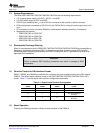
SW001,SW002,andSW003areswitchesforcontrollingtheaudiointerfaceformatoftheDAIreceiver
CS8414.ThedefaultaudiointerfaceformatoftheDSD1796/PCM1795/PCM1796/PCM1798isI
2
S™
format.Table1-1liststhedigitalaudioreceiverconfigurationparameters.
Table1-1.DigitalAudioReceiverConfiguration
ReceiverOutputData
SW001SW002SW003Format
LLL16-to24-bitleft–justified
LHL16-to24-bitl2S
16-bitright-justified(or
HLH
standard)
18-bitright-justified(or
LHH
standard)
PressingtheSW004pushbuttoninitiatesaresetoperationoftheCS8414.
SLEU057A–September2004–RevisedMay2009Description9
SubmitDocumentationFeedback