


Auxiliary equipment
27
En
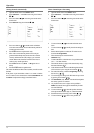
Select from the following possibilities for Source:
Tuner
The tuner signal is looped through and is output from
Scart socket E.
Scart 1
The AV signal is input via Scart socket E, e.g. for video
recorders, analogue satellite receivers, DVD players,
etc.
AV 2
The AV signal is input via Scart socket F, e.g. for video
recorders, analogue satellite receivers, DVD players,
etc.
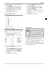
AV 3
(only
23LB020S4,
30LB020S4)
The AV signal is input via Scart socket D, e.g. for video
recorders, analogue satellite receivers, DVD players,
etc.
RGB
The RGB signal (red-green-blue) is fed in via blue Scart
socket and has the best picture quality (most suitable for
digital SAT receivers, DVD players and games con-
soles, etc.)
S-Vid.
The S-VHS signal is fed via the blue Scart socket, e.g.
for S-VHS video recorders, etc.
Additional devices with switching voltage
If, e.g. the video recorder connected to one of the Scart sockets
supplies a so-called switching voltage, the television automati-
cally switches to the appropriate Scart socket (when the PLAY
button on the video recorder is activated). The television set only
reacts when the switching voltage is active. The channel position
can be changed at any time, if necessary.
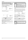
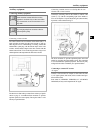
Copy function / recording via Scart sockets
If, for example, a tape is copied from one video recorder to an-
other, recording can take place via Scart sockets D and E. Any
Program can be viewed while being copied. Connect the play-
back video recorder to Scart socket D and the recording video re-
corder to Scart socket E.
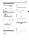
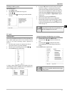
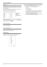
1. Open the Install. menu for this. Press MENU button.
2. Select
Install.
in the Main menu using arrow buttons
Ÿ / ⁄.
3. Press the right-hand arrow button ÿ to move the green
marker in the Install. menu.
4. Select
AV 1 output
out using arrow buttons Ÿ / ⁄.
5. Use the arrow buttons / ÿ to set
AV 2
(15LB020S4,
20LB020S4) or
AV 3
(23LB020S4, 30LB020S4) as the
input signal. The copying procedure can now be started.
6. Press the OK button to store the settings.
7. Press the EXIT button to quit the menu.
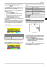
Note:
Pref. menu for Scart 1 out determines which signal is
output at Scart socket E.
This setting is automatically valid for all channel posi-
tions.
Tuner
The tuner signal is looped through and is output from
Scart socket E.
AV 2
The signal from the unit connected to
Scart socket F is available as an output signal
from Scart socket E.
AV 3
(only
23LB020S4,
30LB020S4)
The signal from the unit connected to
Scart socket D is available as an output signal
from Scart socket E.
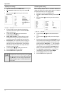
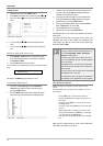
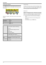
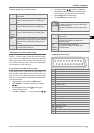
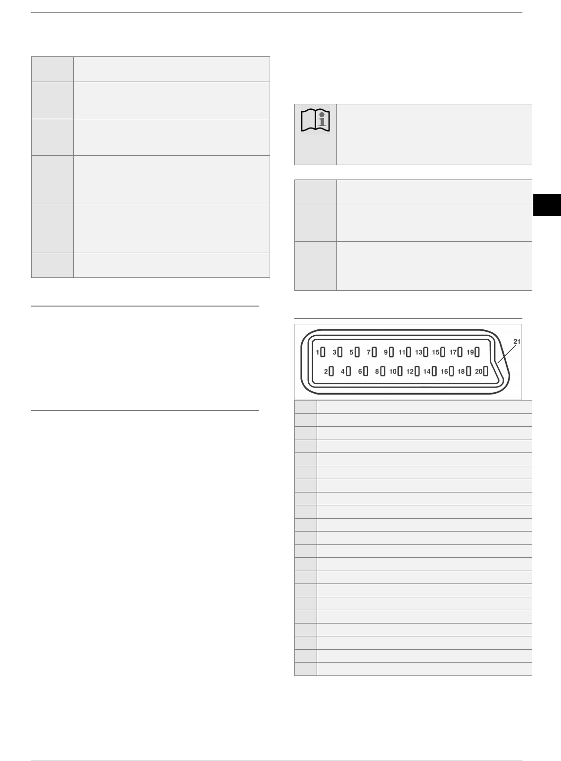
Assigning the Scart sockets
1
Audio out, right
2
Sound input right
3
Sound output left
4
Audio, earth
5
Blue input, ground
6
Audio in, left (mono)
7
Blue input
8
Switching voltage
9
Green input, ground
10
11
Green input
12
13
Red in, earth
14
Fast blanking, ground
15
Red in, S-VHS Chroma
16
Blanking signal, ground
17
Video output, ground
18
Video input, ground
19
Video output
20
Video in, S-VHS Luma
21
Shield
En