Page 3 of 4
Service Bulletin
Commercial Products
Rotaries #16-07
Delayed Deck Engagement
Installation Instructions for PTO Converter Harness (110-8839)
For models 30856, serials 230000101~260000526 & 30868, serials 230000101~260000279
1. Move machine to level surface. Lower cutting units to the ground, stop engine
and remove Key.
2. Remove the Operators Console Cover on the right side of unit.
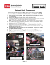
3. Locate the PTO Switch. Disconnect the wire harness connector at the underside
of the switch (pic.1). Pull connector outwards to access wires.
Note: 4 wires on PTO Switch connector. They are blue, pink, orange & brown.
4. Cut the blue wire at the PTO Switch connector. Once cut, re-install the Switch
connector onto the PTO Switch (pic.2).
5. Hold loose blue wire and strip back approx. ¼” of wire insulation. Insert the
stripped blue wire end into the crimp connector of the Converter Harness. Use
suitable pliers to crimp (pic 3).
6. Unplug the male 5 wire connector from the SCM Module. Plug into the female
Converter Harness connector.
7. Plug the male connector of the Converter Harness into the SCM (pic 4).
8. Sit in seat, start unit and engage PTO to ensure proper operation. Reinstall
Console Cover.
SCM
Module
PTO Switch
Harness
1
2
Cut blue wire at connector
3
Strip end of blue wire. Insert
blue wire to PTO Converter
Harness connector and crimp.
4
Converter
Harness
installed


