


– 16 –
GENERAL ADJUSTMENTSSPECIFIC INFORMATIONS
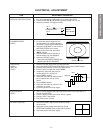
CIRCUIT CHECKS
HIGH VOLTAGE CHECK
CAUTION: There is no HIGH VOLTAGE ADJUSTMENT on
this chassis. Checking should be done following
the steps below.
1. Connect an accurate high voltage meter to the anode of
the picture tube.
2. Turn on the receiver. Set the BRIGHTNESS and CON-
TRAST to minimum (zero beam current).
3. High voltage must be measured below (B) kV.
Refer to table-1 for high voltage (B).
(See SETTING & ADJUSTING DATA on page 17)
4. Vary the BRIGHTNESS to both extremes to be sure the
high voltage does not exceed the limit under any condi-
tions.
CAUTION:
When the following parts fail, check the High Voltage after
replacing.
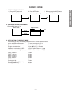
FS CIRCUIT CHECK
The Fail Safe (FS) circuit check is indispensable for the final
check in servicing. Checking should be done following the
steps below.
1. Turn the receiver on.
2. Temporarily short TP- (R) and TP- (X) on the DEF/POWER
Board with a jumper wire.
Raster and sound will disappear.
3. The receiver must remain in this state even after removing
the jumper wire. This is the evidence that the FS circuit is
functioning properly.
4. To obtain a picture again, temporarily turn the receiver off
and allow the FS circuit more than 5 seconds to reset. Then
turn the receiver on to produce a normal picture.
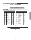
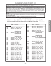
Location
No.
Name
Name
T461
C447
C406
C407
Flyback Trans.
Capacitor
Capacitor
Capacitor
TFB3078ZD
3900pF, ±3%
1500pF, ±3%
4700pF, ±3%
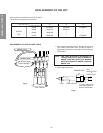
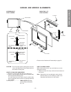
ANODE VOLTAGE MEASURING METHOD
CAUTION: Take extra precaution when measuring this high
voltage. High voltages are also present in
surrounding circuit boards (CRT DRIVE assem-
bly, DEFLECTION assembly, and POWER
SUPPLY assembly).
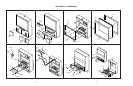
1. Disconnect the FBT anode cable as outlined below. Meas-
ure high voltage at the point where the cable enters the
FBT.
2. Holding the rubber cover firmly, turn it counterclockwise
and check that the lock has been disengaged. (See Fig. b
on page 8.)
3. Determine the extent of the rubber cover before discon-
necting the cable.
4. Pull straight up the anode cable to disconnect.
5. When reconnecting the cable, proceed in the reverse order.
After reconnecting, tug on the cable to check that it is secure.
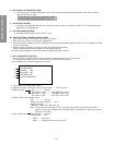
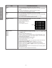
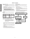
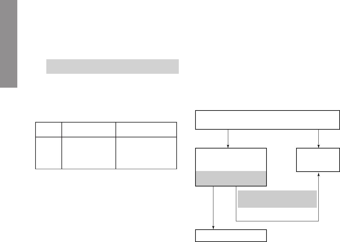
Troubleshooting Guide for Fail Safe Circuit
Check that the set returns to normal operation when
pin 12 of Z801 is grounded with jumper wire.
Check the voltage across
Capacitor C471 is
approximately (
C)
volts.
Refer to table –4 for
fall safe voltage (
C)
.
Faulty power
circuit or hori-
zontal circuit.
Defective Fail Safe Circuit
(See SETTING & ADJUSTING
DATA on page17)
YES NO
NO
YES