


Toshiba 5257Z3500A(E)
32
Connecting your TV
Connecting a computer
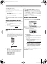
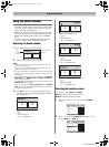
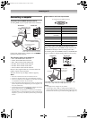
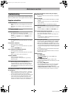
To connect a PC to the RGB/PC terminal on the TV:
An analog RGB (15 pin) computer cable can be connected.
Connect a PC cable from the computer to the o RGB/PC
terminal on the back of the TV.
The following signals can be displayed:
• VGA: VESA 640 5 480 @ 60/75 Hz
• SVGA: VESA 800 5 600 @ 60/75 Hz
• XGA: VESA 1024 5 768 @ 60/70/75 Hz
• W-XGA: VESA 1280 5 768 @ 60/75 Hz
• W-XGA: VESA 1360 5 768 @ 60 Hz
• S-XGA: VESA 1280 5 1024 @ 60/75 Hz
However, these signal formats are converted to match the
number of pixels of the LCD panel.
Therefore, the TV may not display small text properly.
Notes:
• Some PC models cannot be connected to this TV.
• Certain PC signal formats may not be detected correctly.
• There is no need to use an adapter for computers with DOS/
V compatible mini D-sub 15 pin terminal.
• A bar may appear at the edges of the screen, or parts of the
picture may be obscured depending on some signals. This
is not the malfunction.
• If the edges of the picture are stretched, readjust the picture
position adjustments in the PC Setting menu.
• Depending on the specification of the PC you are playing
the DVD-Video on, and the DVD’s title, some scenes may be
skipped, or you may not be able to pause during multi-angle
scenes.
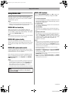
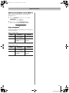
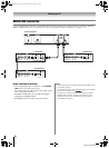
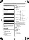
Signal names for mini D-sub 15 pin connector
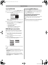
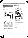
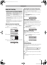
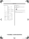
To connect a PC to the HDMI terminal on the TV:
When connecting a PC to the HDMI terminal on the TV, use
an HDMI-to DVI adapter cable and analog audio cables.
If connecting a PC with an HDMI terminal, use an HDMI cable
(type A connector). Separate analog cables are not necessary.
The HDMI input can accept and display VGA, 480i, 480p,
576i, 576p, 720p, 1080i, and 1080p signal formats.
Notes:
• The edges of the images may be hidden.
• If receiving a 720p, 1080i, or 1080p signal program, PC
mode scales the video to display the entire picture within the
borders of the screen (e.g. no overscanning) (
- page 14).
TV back view TV back view
Computer
Audio cable for PC-to-TV connection
Conversion adapter
(if necessary)
RGB PC cable
Mini D-sub 15 pin
Pin No. Signal name Pin No. Signal name
1R9NC
2 G 10 Ground
3B11NC
4 NC (not
connected)
12 NC
5 NC 13 H-sync
6 Ground 14 V-sync
7 Ground 15 NC
8 Ground
5
10
6
15 11
1
Pin assignment for RGB/PC terminal
TV back view TV back view
Computer
Audio cable
for PC-to-TV
connection
5257Z3500.book Page 32 Wednesday, October 24, 2007 6:34 PM