45
Looping Outputs
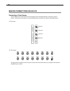
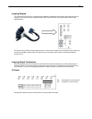
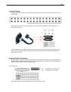
The 8/16 Channel DVS / HVS has up to 16 looping outputs. Depending on the destination of the looping outputs, each one may have
to be terminated.
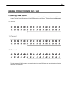
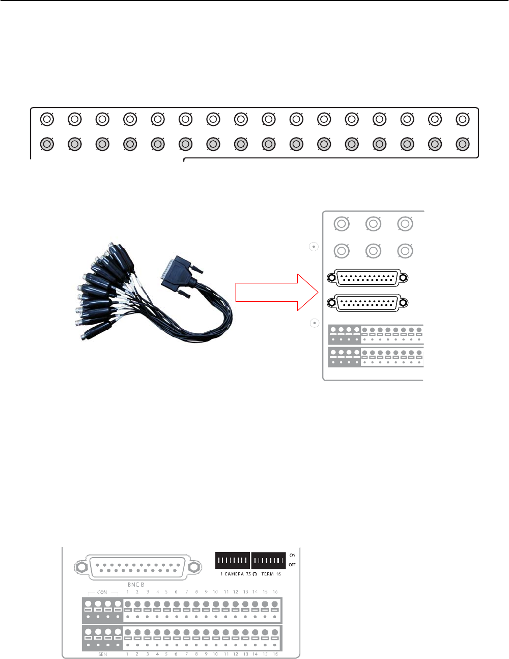
CH 1 in CH 2 in CH 3 in CH 4 in CH 5 in CH 6 in CH 7 in CH 8 in CH 9 in CH 10 in CH 11 in CH 12 in CH 13 in CH 14 in CH 15 in CH 16 in
CH 1 Out CH 2 Out CH 3 Out CH 4 Out CH 5 Out CH 6 Out CH 7 Out CH 8 Out CH 9 Out CH 10 Out CH 11 Out CH 12 Out CH 13 Out CH 14 Out CH 15 Out CH 16 Out
The 32 Channel DVS / HVS has up to 32 looping outputs. Connect the included 16 Channel BNC Connector Cables to the 16
Channel Cable Adapter ports.
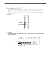
The video inputs/outputs are 75 Ώ BNC connectors. Make sure there is a video source connected to the input and then connect a
cable to the Channel Out on the BNC Connector Cable. The looping outs can be connected to video monitors or combined with
adapters to connect to VCRs.
Looping Output Termination
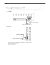
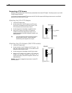
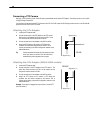
When it is necessary to terminate a looping output, the DVR has built in termination that allows users to select individual outputs. It is
not always necessary to terminate the output; it depends on the device to which you are connecting. As a rule, if the image appears
distorted or virtually unviewable, it likely needs to be terminated.
8/16 Channel
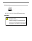
Always leave the dipswitch set to the ON position when the Looping Outputs are not used.
ON Not connected to a monitor (Normal)
OFF Connected to a monitor (Looped)
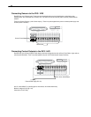
CONT ROL
1 2 3 4 5 6 7 8
COM
SENSOR
ON
OFF
ON
OFF
BNC A
BNC B


