


16
FEATURES
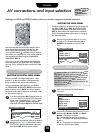
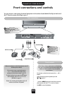
AV connections and input selection
Defining your INPUT and OUTPUT sockets so that your television recognises connected equipment.
…
P
le
a
se
s
e
e
p
a
g
e
2
4
fo
r a
c
le
a
r v
ie
w
o
f th
e
b
a
ck
co
n
n
e
ctio
n
re
co
m
m
e
n
d
a
tio
n
s
…
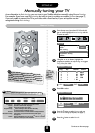
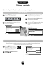
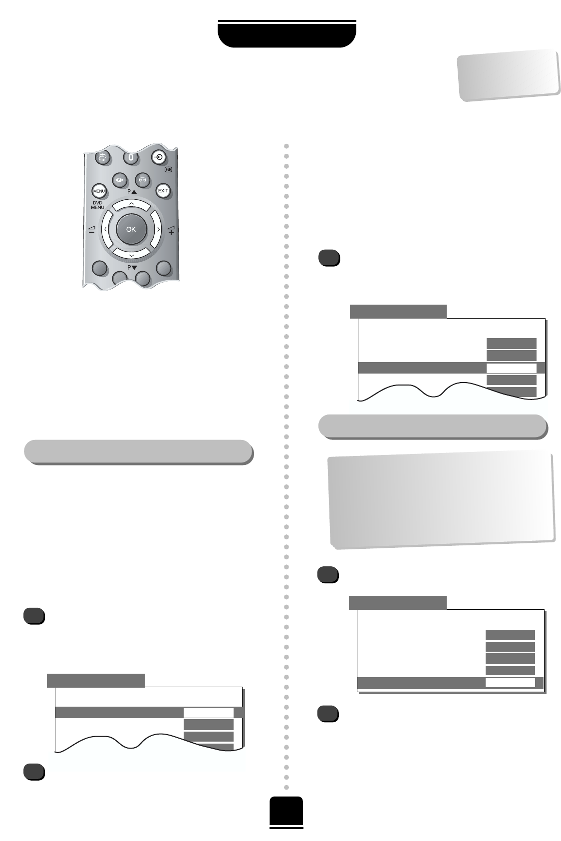
SELECTING THE DIGITAL AUDIO SIGNAL
2
1
▼
▼
▼▼
▼
▼
▼▼
▼▼
Back
Digital input– 1
EXT 4
Digital input– 2
EXT 3
EXT2 input
AV
EXT3 input
S-VIDEO
EXT2 output EXT 1
▼
Input Selection
AV CONNECTION
This set is provided with 2 digital audio inputs – DA-1
and DA-2 – so that, for example, a DVD player and a
games console can stay permanently connected.
Having connected the video signal from your DVD to,
say, COMPONENT VIDEO INPUT (EXT 4) and from your
games console to Scart 3 (EXT 3) you will now need to
connect the audio cables to the inputs on the back of the
set, then match the two up.
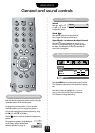
Most video recorders and Set Top Box receivers send a
signal through the Scart lead to switch the TV to the
correct Input socket. Alternatively press the external
source selection button
B
repeatedly until you see the
picture from your equipment. You must use this button to
view equipment connected using the COMPONENT
VIDEO INPUT (EXT 4).
Digital Audio on the screen indicates that the external
source has been set as a digital audio input, see below.
An S e.g. EXT2S, indicates the input is set for an S-Video
signal.
If you have connected to DA-1 (optical), select AV
connection from the FEATURE MENU and press
the Q button to highlight Digital input– 1 then
with the
S
or
R
buttons, select the appropriate
video input, for example EXT 4 for the DVD player.
Then for the 2nd connection, press the Q button to
highlight Digital input– 2 (coaxial) then with the
S
or
R
button, select the appropriate video input,
for example, EXT 3 for the games console.
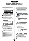
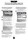
Again, from the FEATURE MENU select AV
connection.
Using the
S
or
R
buttons change the EXT2 output
option to either Monitor, TV, EXT 1 or EXT 3.
Monitor = The picture on screen
TV = The last television programme selection.
EXT 1 = The picture from equipment connected
to Scart 1.
EXT 3 = The picture from equipment connected
to Scart 3 or the front input sockets.
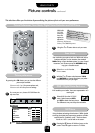
AV CONNECTION
▼▼
▼
▼
▼▼▼
▼ ▼▼
▼
Back
Digital input– 1
EXT 4
Digital input– 2
EXT 3
EXT2 input
AV
EXT3 input
S-VIDEO
EXT2 output EXT 1
2
1
Selecting the OUTPUT signal for Scart 2
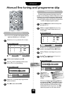
AV CONNECTION
▼▼▼
▼
▼
▼▼▼
▼▼▼
▼
Back
Digital input– 1
EXT 4
Digital input– 2
EXT 3
EXT2 input
AV
EXT3 input
S-VIDEO
EXT2 output EXT 1
This feature allows you to specify the type of signal going
into Scarts 2 (EXT 2) or 3 (EXT 3) on the back of the
television and the sockets on the front (which are also
EXT 3). Please refer to the manufacturer’s instructions
for the connected equipment. If the colour is missing try
the alternative setting.
SELECTING THE VIDEO SIGNAL
1
From the FEATURE MENU select AV connection
and with the
S
or
R
button select either AV or
S-VIDEO as the required input for EXT2 and
EXT3.
This feature enables you to select the source to output
from
Scart 2.
e.g. If you connect a stereo Set Top Box
to Scart 1
and a stereo video recorder to Scart 2, and
select EX
T 1
as the EX
T2
output (i.e. you w
ill output
the signal received through Scart 1 directly out to
Scart 2
), you w
ill be able to record the stereo Set Top
Box tran
sm
ission in stereo.