


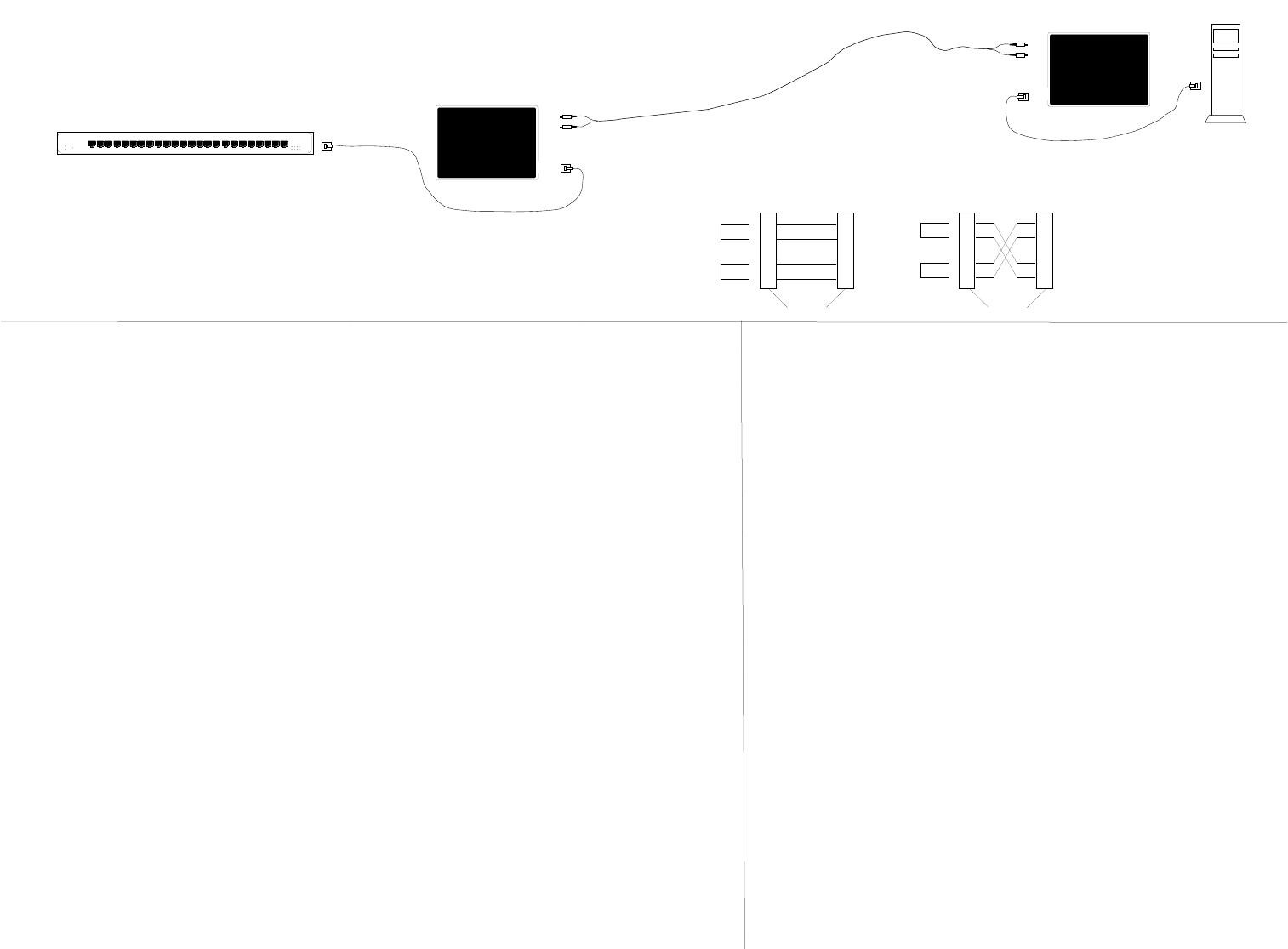
straight-through
crossover
<100 meters
Fileserver
<100 meters
25 Mb/s or 155 Mb/s ATM Switch
2 kilometers - multimode
20 kilometers - singlemode
Straight Through/Crossover Cable Requirements and Pin Specifications
The two active pairs in an
ATM network are pins 1 & 2
and pins 7 & 8. Use only
dedicated wire pairs (such as
blue/white & white/blue,
orange/white & white/orange)
for the active pins.
1. Is the power LED on the media converter illuminated?
NO
• Is the power adapter the proper type of voltage and cycle frequency for your AC outlet?
NOTE: Refer to the “Power Supply Requirements” on the back page.
• Is the power adapter properly installed in the media converter and in the outlet?
• Contact Technical Support at (800) 260-1312/ (800) LAN-WANS.
YES
• Proceed to step 2.
2. Is the TX Activity LED illuminated?
NO
• Check UTP cables for proper connection and pin assignment. (See above.)
• Contact Technical Support at (800) 260-1312/ (800) LAN-WANS.
YES
• Proceed to step 3.
3. Is the Fiber Activity LED illuminated?
NO
• Check fiber cables for proper connection.
• Verify that TX and RX cables on media converter are connected to RX and TX ports,
respectively, on the other 100BASE-FX device.
• Refer to Tech Tips available at: http://www.transition.com
• Contact Technical Support at (800) 260-1312/ (800) LAN-WANS.
YES
• Contact Technical Support at (800) 260-1312/ (800) LAN-WANS.
• KEEP TWISTED-PAIR RUNS AS SHORT AS POSSIBLE.
• Connect the power supply cable to the media converter BEFORE connecting to the outlet.
• Install unit with PSU provided. (Output 9 VDC regulated, 500 mA).
Troubleshooting the Media Converter
Installation Notes
If the ATM media converter fails, determine the answers to the following questions:
Twisted
Pair #1
Twisted
Pair #2
Crossover Cable
Connectors for like devices
1
2
7
8
1
2
7
8
1
2
7
8
Twisted
Pair #1
Twisted
Pair #2
Straight Through Cable
Connectors for unlike devices
1
2
7
8
Be certain that the twisted-pair cable is configured
correctly (straight through or crossover) for site. Cable
connections between an ATM switch and the media converter must
be configured as straight through. Cable connections between the
media converter and a NIC must be configured as crossover.
The physical characteristics of the media cable must meet or exceed the
specifications: ATM UNI 3.1 #AF-PHY-0015
Maximum number of media converters in series: 2
ATM CABLE SPECIFICATIONS
FIBER CABLE SPECIFICATIONS
SINGLEMODE
Fiber Optic Cable Recommended: 9 µm singlemode fiber
Fiber Optic Transmitter Power: min: -15.0
dBm max: -8.0 dBm
Fiber Optic Receiver Sensitivity: min: -31.0 dBm max: -8.0 dBm
Wavelength: 1300nM
Bit error rate: ≤10
-9
Maximum Cable Distance: 20 kilometers
MULTIMODE
Fiber Optic Cable Recommended: 62.5 / 125 µm multimode fiber
Optional: 100 / 140 µm multimode fiber
85 / 125 µm multimode fiber
50 / 125 µm multimode fiber
Fiber Optic Transmitter Power: min: -19.0 dBm max: -14.0 dBm
Fiber Optic Receiver Sensitivity: min: -30.0 dBm max: -14.0 dBm
Wavelength: 1300nM
Bit error rate: ≤10
-9
M i C bl Di 2 kil
COPPER CABLE SPECIFICATIONS
Category 5 wire or better is required. Either shielded twisted-pair (STP) or
unshielded twisted-pair (UTP) can be used. DO NOT USE FLAT OR SILVER
SATIN WIRE.
Category 5:
Gauge 24 to 22 AWG
Attenuation 20 dB/1000’ @ 10 MHz
Impedance 100 Ω ±10% @ 10 MHz
Maximum Cable Distance: 100 meters (330 feet)
A-CF-01