


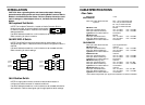
INSTALLATION
(continued)
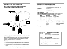
Install Cable
COPPER
T1 100 OHM (RJ-45 CONNECTOR)
1. Locate or build twisted-pair cables that are compliant with
specifications on page 10, with RJ-45 plug connectors at both ends.
2. Ensure that MDI/MDI-X switch is set according to network
conditions.
3. Connect RJ-45 plug connector at one end of cable to media
converter RJ-45 jack connector.
4. Connect RJ-45 plug connector at other end of cable to network
equipment.
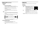
FIBER
1. Locate or build fiber cables that are compliant with specifications
on page 9, with male two-stranded TX to RX connectors installed at
both ends.
2. Connect cable with connector installed at TX location on media
converter to RX location on attached device.
3. Connect cable with connector installed at RX location on media
converter to TX location on attached device.
Power the Media Converter
1. Install power adapter cord at back of media converter.
2. Connect power adapter plug to AC power.
3. Verify that media converter is powered by observing illuminated
LED(s).
OPERATION
After installation, the media converter should function without operator
intervention.
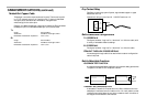
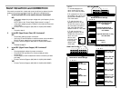
Status LEDs
Use the status LEDs to monitor media converter operation in the network.
SDC Signal Detect/Copper - Steady LED
indicates twisted-pair copper link is up.
Flashing LED (once/second) indicates
transmitting on link if other link is down.
Flashing LED (5 times/second) indicates
All Ones detected on Link.
SDF Signal Detect/Fiber - Steady LED indicates fiber link is up.
Flashing LED (once/second) indicates transmitting on link if
other link is down.
Flashing LED (5 times/second) indicates All Ones detected on
Link.
P(o)W(e)R Steady green LED indicates connection to external AC power.
PWR
SDF
SDC
LOOP
TX
RX
TX
RX