


1. Introduction........…………………….....................….....………….............
2. Features....................................................................................................
3. Package Contents....................................................................................
4. Operation Controls and Functions.........................................................
4.1 Top Indicator Panel..........................................................................
4.2 Right Input Panel.............................................................................
4.3 Left Output Panel............................................................................
4.4 Back Input Selection Panel..............................................................
5. Audio Performance Levels......................................................................
5.1 Analog Audio Input..........................................................................
5.2 Digital Coax Input.............................................................................
5.3 Digital Optical Input........................................................................
6. Audio Input to Output Comparison Chart............................................
7. Connection and Installation...................................................................
8. Specifications...........................................................................................
AC200
2
2
2
3
3
3
4
4
5
5
5
5
5
6
6
1
4. Operation Controls and Functions
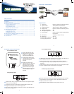
4.1 Top Indicator Panel
Power LED Indicator light:
When the LED is green the
AC200 is on, a RED light
indicates the AC200 is off.
Analog LED Indicator light:
The blue LED will illuminate
when the L/R input is
selected.
Digital Coax Audio LED
Indicator light: The blue LED
light will illuminate when
the COAX input is selected.
Optical LED Indicator light:
The blue LED will illuminate
when the Optical input is
selected.
1
2
6
3 4
1
2
3 3
2
1
1
2 3
1 2 3
4
2 31
2 31
3
4
4.2 Right Input Panel
Optical Input: Using an Optical cable connect to the Optical output
of your source equipment.
Coax Input: Using a 75 ohm digital coaxial cable connect to the
Digital Coax output of your source equipment.
L/R Input: Using an Analog Audio pair connect to the L/R output of
your source equipment.
1
2
1
2 3
1 2 3
4
2 31
2 31
3
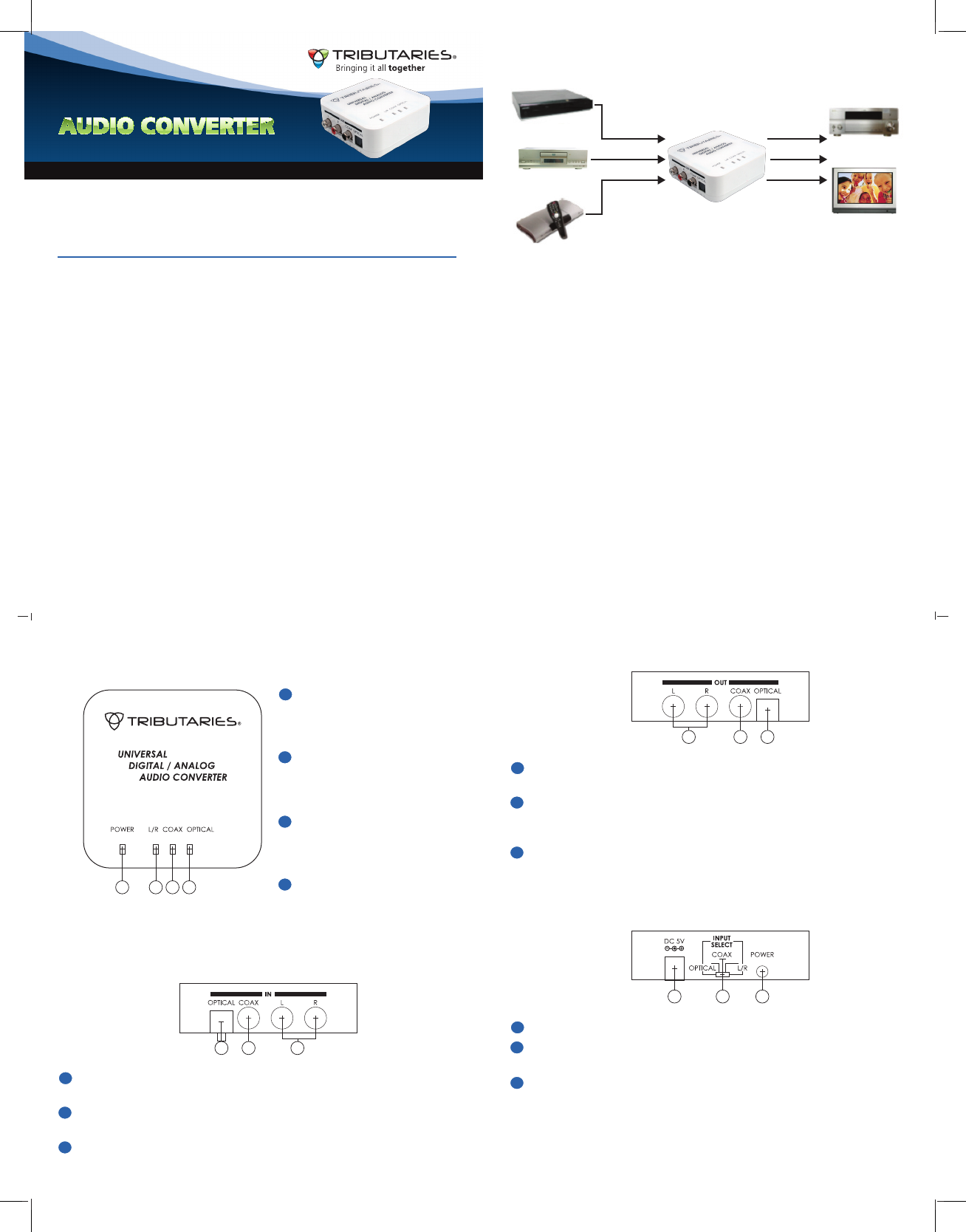
4.3 Left Output Panel
L/R Output: Using an Analog Audio pair connect to the L/R Input of
your equipment such as TV, Receiver or Amplifier.
Coax Output: Using a 75 ohm digital coaxial cable connect to
the Digital Coax Input of your equipment such as TV, Receiver or
Amplifier.
Optical Output: Using an Optical cable connect to the Optical Input
of your equipment such as TV, Receiver or Amplifier.
1
2
1
2 3
1 2 3
4
2 31
2 31
3
4.4 Back Input Selection Panel
DC 5V: Connect the 5 volt power supply (included) to your AC outlet.
Input Selector: Use this switch to select appropriate input from
Optical, Coaxial or L/R audio.
Power Button: Push this button to turn power on or off.
1
2
1
2 3
1 2 3
4
2 31
2 31
3
7. Specifications
Input Ports: Optical, Coaxial and L/R Analog Audio1.
Input Formats: Toslink, SPIDIF and LPCM 2CH2.
Sample Frequency: 32kHZ, 44.1KHz, 48KHz and 96KHz3.
Output Ports: Optical, Coaxial and L/R Analog Audio4.
L/R Input Impedance: 47K 5. Ω
L/R Output Impedance: 47K 6. Ω
Power Supply: 5V/ 1A, Universal Power Supply CE/FCC/ 7.
UL Certified
Dimensions: 3.8”(W) x 3.4”(D) x 1.4”(H)8.
Weight (g): 4.25 oz.9.
Operating Temperature: 32F - 104F10.
Storage Temperature: -4F - 140F11.
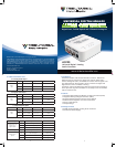
DVD PLAYER
OR
BLU RAY
OR
SET-TOP BOX
AMPLIFIER
OR
TV
L/R
OPTICAL
COAXIAL
L/R
OPTICAL
COAXIAL
6. Connection and Installation
Table of Contents
UNIVERSAL DIGITAL/ANALOG
Digital Coax, Toslink Optical and 2 Channel Analog R/L