


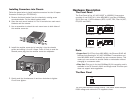

Installing Converters into Chassis
Follow the steps below to install modular converters into the 10 space
Converter Chassis (pn: FEP-593110).
A. Remove the blank bracket from the chassis by rotating screw
counterclockwise. Put the blank bracket aside.
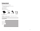
B. Open the rack mount bracket kit. The kit contains two rack mount
brackets and four screws.
C. Use a screwdriver to attach the rack mount ears to both sides of
the modular converter.
D. Install the modular converter by inserting it into the chassis
guides and sliding it in until it stops. Press it firmly to seat the
chassis power plug into the modular converter receptacle.
E. Gently push the thumbscrews in and turn clockwise to tighten.
Do not over tighten.
7 4
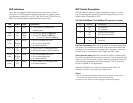
Hardware Description
The Front Panel
The Front Panel of the 10/100/1000T to 1000SX/LX converters
consists of one RJ-45 Port ( Auto MDI/MDIX ) one fiber 1000Base-
SX/LX Port and 6 LED Indicators (SPD, LK/ACT, FDX, Fiber LK/ACT,
FDX/COL and PWR ).
Ports
• Copper Port: RJ-45 Port (Auto MDI/MDIX), the Ethernet RJ-45 will
features Auto-Sensing for 10/100/1000Base-T connections and
Auto MDI/MDIX which is basically an auto crossover feature. This
means you can connect to another Switch or workstation without
changing to a crossover cable.
• Fiber Port: This port is for the 1000Base-SX/LX connection and is
available in the SC format in Multi- and Single mode.This fiber port
does not support auto-negotiation.
The Rear Panel
The rear panel contains a power socket. This power socket accepts
DC9V voltage and minimum 0.7A supplied current.
Multi-ModeAuto MDI/MDIX
10/100/1000T
100Base-SX
LK/ACT
F
DX/CO L
SPD PWR
1 2 3
ON
Single ModeAuto MDI/MDIX
1
0/100/1000T
1000Base-LX
L
K/ACT
FDX/CO L
SPD PWR
1
2 3
ON
GEP-5300TF-C 550m
GEP-5400TF-C 10km
DC IN
A
u
t
o M
D
I
/M
D
I
X
1
0
/
1
0
0
/
1
0
0
0
T
1
0
0
B
a
s
e
-
S
X
S
P
D