


Installation
22 Vidikron PlasmaView VHD Installation/Operation Manual
PRE
L
IMINAR
Y
3.4
Connections to the
PlasmaView VHD and VHD
Controller
Proceed as follows to connect the PlasmaView VHD to the VHD Controller, your video
sources, external controller(s) – if present – and AC power.
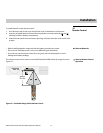
When connecting your equipment:
• Turn off all equipment before making any connections.
• Use the correct signal cables for each source.
• Ensure that the cables are securely connected. Tighten the thumbscrews on connectors
that have them.
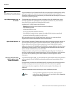
Connecting the PlasmaView
VHD to the VHD Controller
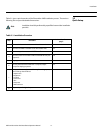
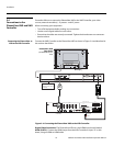
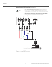
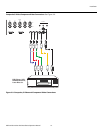
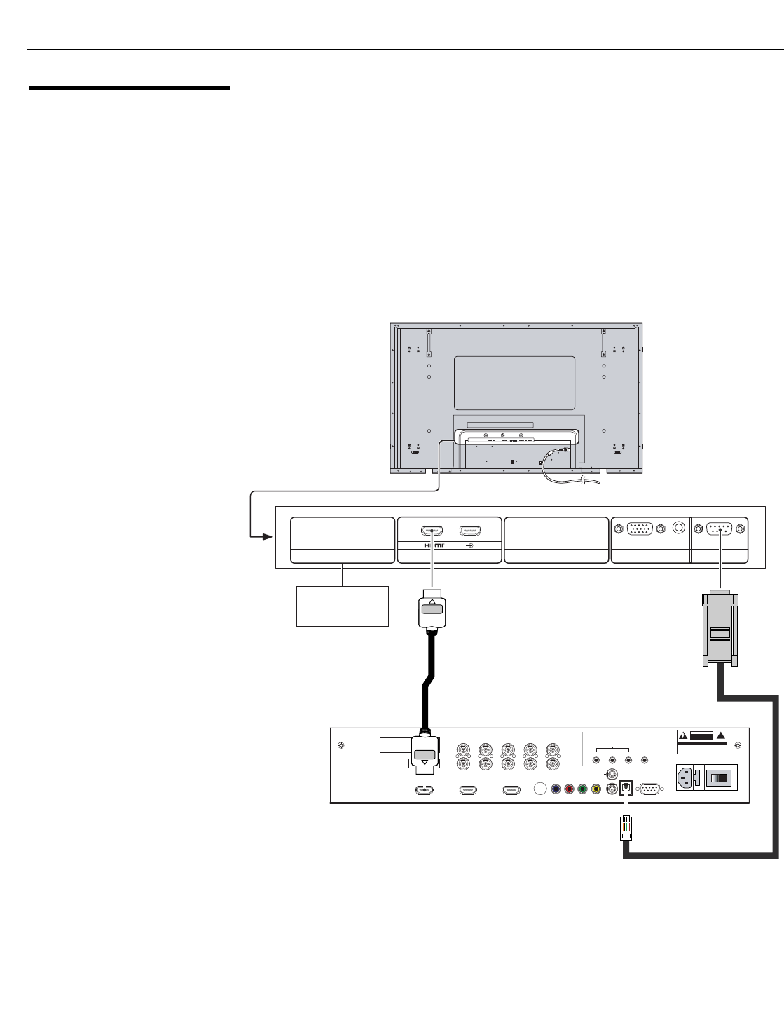
Connect the VHD Controller to the PlasmaView VHD as shown in Figure 3-4 and described in
the sections that follow.
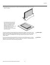
Figure 3-4. Connecting the PlasmaView VHD to the VHD Controller
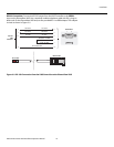
Digital Video Connection: The PlasmaView VHD has a dual HDMI input board, labeled
HDMI (SLOT 2). Connect the HDMI output from the VHD Controller to input “A” on this
board, using an HDMI-to-HDMI cable.
➤
Pb Pr Y
Video
3
IR
RS-232 Control
S-Video 1
S-Video 2
HD1
HD2
1
2
R/Pr G/Y B/Pb
R/Pr G/Y B/Pb H V
HDMI 1 HDMI 2HDMI Out
HV
TRIGGERS
RS-232 Out
CAUTION: TO REDUCE THE RISK OF ELECTRIC
SHOCK, DO NOT REMOVE COVER. NO USER-
SERVICEABLE PARTS INSIDE. REFER SERVICING
TO QUALIFIED SERVICE CENTER.
AVIS: RISQUE DE CHOC ELECTRIQUE-NE PAS OUVRIR
CAUTION
RISK OF ELECTRIC SHOCK
DO NOT OPEN
!
WARN ING:
TO REDUCE THE RISK OF FIRE
OR ELECTRIC SHOCK, DO NOT EXPOSE
THIS APPLIANCE TO RAIN OR MOISTURE.
100-230VAC 50-60 Hz, 165 Watts Max
INPUTS
SYSTEM CONTROL INTERFACE
Component Video
SDI
Option
Serial No
Video Processor / Controller
Model
Made In USA
SERIALPC IN
AUDIO
SLOT1 SLOT2
Optional Terminal
Board Insert Slot
(covered)
AV IN
AB
HDMI OUT
RS-232
OUT
PlasmaView VHD
Rear Panel
(VP-6500VHD shown
here)