


6
AUDIO (L)
VIDEO
LINE-1
AUDIO
L
R
(MONO)
VIDEO
LINE-1
UHF/VHF
AUDIO
L
R
(MONO)
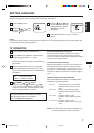
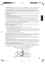
This television has an extended
tuning range and can tune most
cable channels without using a
cable company supplied
converter box. Some cable
companies offer “premium pay
channels” in which the signal is
scrambled. Descrambling these
signals for normal viewing
requires the use of a descrambler
device which is generally
provided by the cable company.
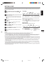
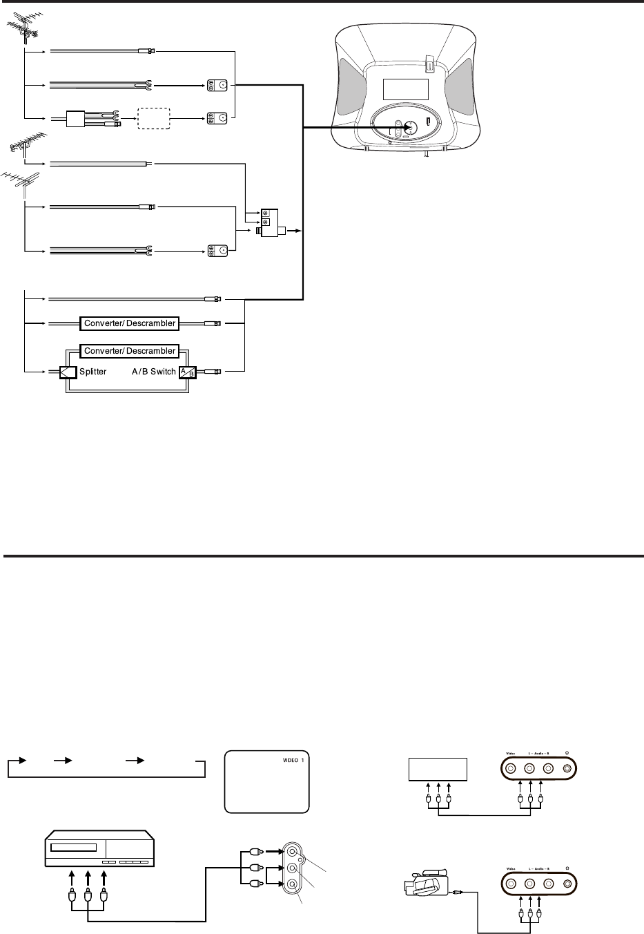
ANTENNA/CATV CONNECTIONS
Separate UHF/VHF Antennas
Connect the 75 ohm Cable from the VHF antenna and the UHF
antenna Twin-lead to a combiner (not supplied). Attach the Combiner
to the Antenna Jack.
NOTE: If your VHF antenna has a Twin-lead Wire, use the 300-75
ohm Matching Transformer (not supplied), then connect the
Transformer to the Combiner.
For Subscribers to Basic Cable TV Service
For basic cable service not requiring a Converter/Descrambler box,
connect the CABLE TV 75 ohm Coaxial Cable directly to the
Antenna Jack on the back of the television.
For Subscribers to Scrambled Cable TV Service
If you subscribe to a cable service which requires the use of a
Converter/Descrambler box, connect the incoming cable to the
Converter/Descrambler box and connect the output of the box to the
Antenna Jack on the back of the television. Follow the connections
shown left. Set the television to the output of the Converter/
Descrambler box (usually channel 3 or 4) and use the Converter/
Descrambler box to select channels.
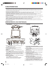
For Subscribers to Unscrambled Basic Cable with Scrambled
Premium Channels
If you subscribe to a cable service in which basic cable channels
are unscrambled and premium channels require the use of a
Converter/Descrambler box, you may wish to use a two-set signal
splitter (sometimes called a “two-set coupler”) and an A/B Switch
box from the cable installer or an electronics supply store. Follow
the connections shown left. With the switch in the “B” position, you
can directly tune any nonscrambled channels on your TV. With the
switch in the “A” position, tune your TV to the output of the Converter/
Descrambler box (usually channel 3 or 4) and use the box to tune
scrambled channels.
300-75 ohm
Matching Transformer
(not supplied)
Combiner
(not supplied)
300-75 ohm
Matching Transformer
(not supplied)
VHF Antenna
Incoming CABLE TV
Single 75 ohm Cable
Combination UHF/VHF Antenna
300 ohm Twin-lead Wire
Splitter
Take off the Splitter
Single 75 ohm Cable
300 ohm Twin-lead Wire
300 ohm Twin-lead Wire
UHF Antenna
Combination UHF/VHF Antenna (Single 75 ohm Cable or 300
ohm Twin-lead Wire)
Connect the 75 ohm cable from a combination UHF/VHF antenna to
the Antenna Jack. If your combination antenna has a 300 ohm Twin-
lead Wire, use the 300-75 ohm Matching Transformer (not supplied).
Combination UHF/VHF Antenna (Separate VHF and UHF 300
ohm Twin-leads)
Connect the UHF Twin-lead Wire to a Combiner (not supplied).
Connect the VHF Twin-lead to the 300-75 ohm Matching
Transformer (not supplied).
Attach the Transformer to the Combiner.
Attach the Combiner to the Antenna Jack.
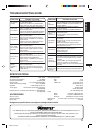
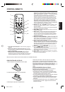
If you connect the TV to a VCR or DVD for playback, or if you
connect a camcorder or Video Game System, you can make your
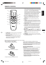
selection by pressing the VIDEO (or TV/AV) button.
Press the VIDEO (or TV/AV) button repeatedly to select the
desired mode.
“VIDEO 1” or “VIDEO 2” will display on the screen for 4 seconds.
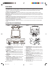
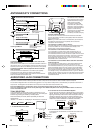
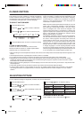
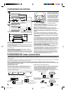
AUDIO/VIDEO JACK CONNECTIONS
The exact arrangement you use to interconnect various video and audio components to the TV is dependent on the model and features of each
component. Check the Owner's Manual provided with each component for the location of video and audio inputs and outputs.
The connection diagrams below are offered as suggestions. You may need to modify them to accommodate your particular assortment of
components. The diagrams are intended to show component video and audio interconnections only.
Press the VIDEO button or TV/AV button on the unit to select the AV mode to use the TV as a monitor.
This TV is designed to output stereo sound (audio signal from AUDIO L/R) ONLY when using the AUDIO IN Jacks on either the
front or the back of the unit.
To playback from the camcorder, connect the camcorder to the
TV as shown.
3. To connect the TV to the Camcorder
The TV can also be used as a display device for many video
games. However, due to the wide variety of different types of
signal generated by these devices and subsequent hook-up
variations required, they have not all been included in the
suggested connection diagrams. You'll need to consult each
component's Owner's Manual for additional information.
2. To connect the TV to a Video Game System
1. To connect the TV to a VCR
Rear of TV
VCR
To Audio/Video
OUT
VIDEO
AUDIO (R)
TV/AV SELECTION
(not supplied)
Front of TV
(not supplied)
To Audio/Video OUT
Front of TV
To AV OUT jack
(not supplied)
TV VIDEO 1 VIDEO 2
Video Game System
3P90231D -E/P02-07 7/7/05, 14:446