


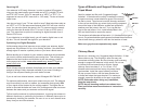
Using Preampliers and Distribution Ampliers
Ampliers do not increase the antenna’s signal. Ampliers can overcome
any cable and splitter loss to improve signal strength at the tuner. They help
get the signal to the tuner in installations with multiple TVs or long cable
runs in weak signal areas. Long cable runs result in 50% loss of signal for
every 100 ft of RG6.
Avoid using preamps and ampliers in urban areas, as the strong signal in
these areas may be overdriven by additional amplication.
Cable Selection
RG6 is now the industry standard for coaxial cable. The greatest advantage
to using this cable over the traditional RG59 is a bit less cable loss. RG6
is rated at -6dB loss per 100’ run, while RG59 is rated at -8dB loss for the
same run. This could be a consideration if cable loss is a factor in your
installation.
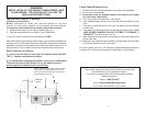
Antennas are often returned that are in perfect working order. Be sure
to check all connectors for proper installation and t, or for corrosion on
existing installations and perform a channel scan anytime you have a
reception problem.
Troubleshooting Ideas
• Rotate and Rescan. Many signal problems can be solved by re-aiming
your antenna.
• If the antenna is indoors, try a different location and rescan.
• Check coax for corrosion and shorts.
• If you are having trouble receiving signal, try a direct connection from the
antenna to the tuner with a new coax cable.
• Run a new channel scan once each month to nd new channels that
are added to your area or if you have moved the antenna.
• Check the knowledge base http://www.winegard.com/kbase/index.php
• Call Winegard, 1-800-788-4417
3
6
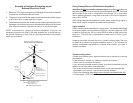
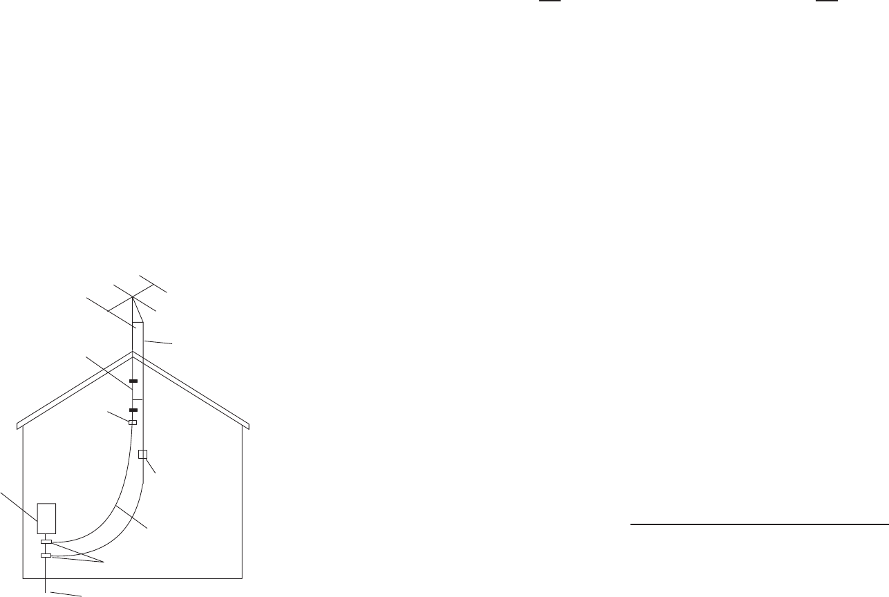
Example of Antenna Grounding as per
National Electrical Code
1. Mount the 75 ohm grounding block or discharge unit as close as possible
to where the downlead enters the house.
2. The ground wires for both the mast and the downlead should be copper
or aluminum wire, number eight (8) or larger.
3. The downlead wire from the antenna to the antenna grounding block or
discharge unit and the mast ground wire should be secured to the house
with stand-off insulators, spaced from four (4) to six (6) feet apart.
NOTE: In the case of a “ground up” antenna installation, it may not be
necessary to ground the mast if the mast extends four or more feet into
the ground. Consult your local code or a licensed electrician for the proper
depth in your location.
Antenna Lead
In Wire
Ground
Clamp
Electric
Service
Equipment
Antenna
Discharge Unit
(NEC Section 810-21)
Power Service Grounding
Electrode System
(NEC Art 250, Part H)
Ground
Clamps
NEC - National Electrical Code
Example of antenna grounding as per
National Electrical Code, ANSI/NFPA 70
Grounding Conductor
(NEC Art 250, Part H)
Antenna Mast
75 ohm coax
Grounding Block