


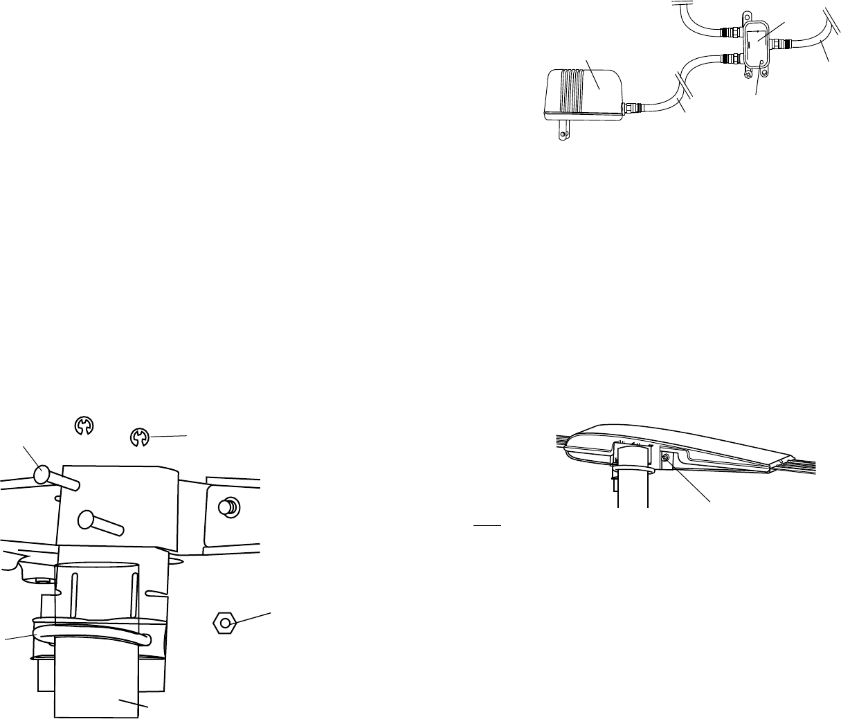
AC ADAPTOR
(SUPPLIED)
6’ STANDARD
COAX CABLE
(SUPPLIED)
COAX CABLE TO DIGITAL
TV, DIGITAL CONVERTER
BOX, DISTRIBUTION AMP
OR SPLITTER
LED
POWER IN
ANT.
DOWNLEAD COAX CABLE FROM
PREAMP OR AMPLIFIED ANTENNA
POWER
INJECTOR
TV
Figure 2
(2) E-Clip
(2) Pin
(2) Hex Nut
Mast Bracket
U-Bolt
Mast Clamp
against Bracket
Figure 1
WARNING:
INSTALLATION OF ANTENNAS NEAR POWER LINES IS DANGEROUS.
FOR YOUR SAFETY, FOLLOW THE INSTALLATION INSTRUCTIONS.
INSTALLATION
This SENSAR antenna may be installed inside or outside on any mast or
pole. DO NOT MOUNT OVER CHIMNEY OPENING.
STEP 1. Make sure "W" opening is on bottom side of antenna head, foot
embossing points down. Slide metal mounting bracket up into back bracket
on antenna and attach with pins and E-clips. See Figure 1.
STEP 2. Insert "U" bolt thru mast clamp and mast bracket and start hex
nuts onto "U" bolt. See Figure 1.
STEP 3. Slide mast thru "U" bolt and tighten hex nuts with 7/16"
wrench.
Model GS-1100 (Non-amplied Models ONLY)
Attaching Downlead Cable
STEP 4. Attach downlead coax cable to F-jack on back of antenna head
and tighten securely. (Figure 3). Tape downlead to mast and run coax cable
to TV. Point the front of the antenna (with Winegard logo) at broadcast
towers of stations you want to receive.
STEP 5. Attach "F" connector to downlead and connect to "F" jack on TV.
Models GS-2200 (Amplied Models ONLY)
Attaching Downlead Coax Cable
If using the power supply, follow these steps.
STEP 4. Attach “F” connector on downlead coax cable to the power injector jack
marked “ANTENNA”. Point the front of the antenna (with Winegard logo) at broadcast
towers of stations you want to receive
STEP 5. Attach “F” connector on coax cable from DTV, Digital Converter box,
Distribution Amplier, or splitter system to jack on Power Injecter marked TV.
STEP 6. Connect one “F” connector on supplied black RG-6 coax cable to the power
injector jack marked “PWR IN”. Connect the other “F” connector on supplied RG-6
coax cable to jack on supplied AC wall transformer. See Figure 2. You can use a
longer piece of RG6/U coax cable if required up to 100 feet between the AC adaptor
and power insertor if required.
STEP 7. Mount the power injector to the wall using supplied screws. Plug in AC
wall transformer to household wall outlet.
TIPS:
If splitting the signal to multiple TVs or combining with another signal source, it is
strongly recommended that the power injector be installed between the antenna
and the splitter/combiner input. In this case, the cable connection from the “TV”
jack of the power injector goes to the splitter input or valid combiner input. Use
splitters rated from 54-806 MHz or wider bandwidth (commonly 5-1000 MHz) for
over-the-air television signal distribution.
Additional distribution/inline ampliers must be installed FOLLOWING the TV output
of the power injector, NOT on the downlead cable line connecting to the ANTENNA
port. Check TV picture quality, if the power injector LED is glowing when powered,
and antenna alignment prior to adding additional line ampliers.
A maximum antenna-to-power injector length of 150 feet RG-6 or 150 feet RG-59
is acceptable.
Pipe
Figure 3
Attach coax here.