


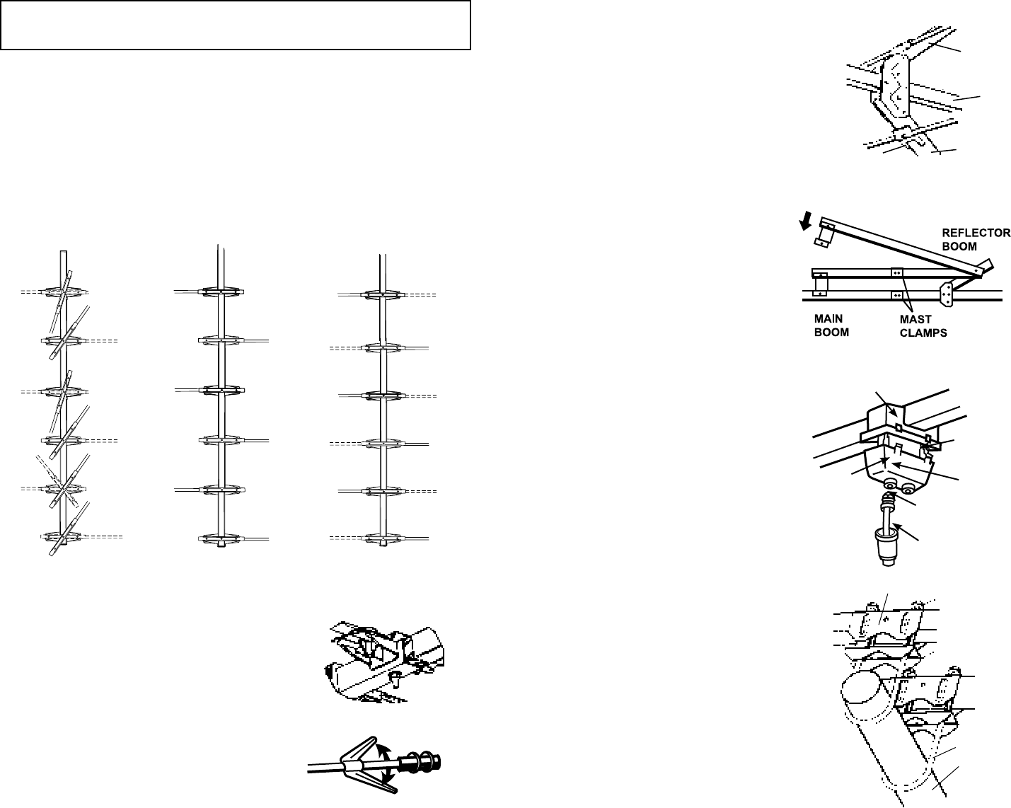
STEP 10. To attach the cartridge hous-
ing to the antenna, align the snaps on the
cartridge housing with the snap holes on
the cartridge housing receptacle on the
antenna and push the housing into the
receptacle until it snaps into place. See
Figure 8.
STEP 11. Attach the 75 ohm coaxial cable
to the cartridge housing. See Figure 8.
Slide weather boot over connector and
boot collar.
STEP 12. To mount the antenna on the
mast, loosen nuts on the main boom and
boom brace mast clamps. Slide both mast
clamps over the mast pointing the front of
the antenna (small end) towards stations
and tighten the boom brace mast clamp
securely. Let the main boom mast clamp
slide down the mast until the boom brace
supports the main boom. Tighten the main
boom mast clamp securely. See Figure 9.
STEP 13. The 75 ohm coaxial cable down-
lead may be secured to the mast by either
taping it or use of plastic wire ties.
Fig. 5
STEP 7. Unfold the reector booms
slowly until they lock in place. Then
unfold the elements on the reector
booms. See Figure 6.
STEP 8. To install the boom brace
remove the bolts and hex nuts. Attach
the boom brace to the reector boom
rst, making sure that the mast clamps
are on the same side, see Figure 7. Do
not tighten the bolt and hex nut.
STEP 9. Swing the boom brace down
onto the main boom and insert the bolt
and hex nut, see Figure 7. Tighten both
bolts and hex nuts securely.
Fig. 6
MASTING
2" OD MAX.
MAST CLAMP
MAST CLAMP
INSERT
HEX NUT
U-BOLT
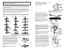
STEP 5. Unfold the elements of the front
section of the antenna. The elements should
be on the top side of the front section of the
antenna. Remove the bolt and hex nut, (see
Fig 4) from the tapered end of the front boom
and slide the tapered end into the front of the
rear boom. The cartridge housing receptacle
on the rear section of the antenna is attached
to the bottom of the rear boom at the factory.
Replace the bolt, and hex nut. Tighten
securely.
STEP 6. Unfold UHF directors, as shown in
Figure 5.
NOTE:
To prevent damage in shipping, the second set of elements from the rear of the
boom are folded to the opposite side.
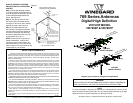
STEP 2. Grasp both ends of the second element from the rear of the boom. Lift
the ends of the element just enough to slide over the other elements to the front
and rear and ROTATE ABOUT 100° COUNTER CLOCKWISE to lock. See Fig. 1.
STEP 3. Unfold the rest of the elements on this side of the antenna to the lock
position, being sure to alternate the elements. See Figure 2.
STEP 4. Turn the antenna over and repeat steps 1, 2 and 3. Again lift and rotate
the second element just enough to slide over the other elements. See Figure 3.
Fig. 4
Fig. 7
Fig. 8
Fig. 9
Fig. 1
Fig. 3
Fig. 2
Antenna shown from top
side with front of rear sec-
tion pointing away from you.
Antenna shown from under-
side with front of rear section
pointing away from you.
STEP 1. Remove the rear section of antenna from carton (long elements). Lay
it on the ground with the end with the plug pointing toward you. Starting with the
element nearest you, unfold the rst element CLOCKWISE about 80° and click to
lock position. See Figure 1.
CARTRIDGE HOUSING
RECEPTACLE
75 OHM COAXIAL
CABLE (DOWNLEAD)
BOOT
COLLAR
CARTRIDGE
HOUSING
DOWNLEAD
JACK
WEATHER BOOT
MAIN
BOOM
REFLECTOR
BOOM
REFLECTOR
BOOM
ENDS OF CLIPS
SHOULD POINT AWAY FROM MAIN BOOM
Lift and
Rotate