


Step 1: Contents of Package
A. Remove all parts from the box and compare to the parts list to ensure
nothing is missing and to become familiar with the part names.
Note: Unfolding elements procedure is the same for both HD7698P &
HD8200U antennas.
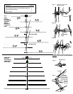
Step 2: Rear Section
A. Stand rear section up vertically with U-bolt assembly up and cartridge
housing facing away from you.
B. Unfold elements per Figure 1 in direction of arrows until they lock into
place in the black plastic blocks.
C. Spin the rear section around so the cartridge housing is now facing you.
D. Unfold the remaining elements so they point in the opposite direction from their
matching half which was unfolded in step 2B above.
E. Set rear section aside being careful not to bend the elements (laying it
at on the ground is the best position).
Step 3: Front Section
A. Stand front section up vertically with the shortest element down and
elements facing you.
B. Unfold all elements (in any order) until they snap in place.
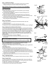
C. Remove bolt, hex nut, and director element from front section boom. See Fig. 2.
Step 4: Attaching Front Section to Rear Section
A. Slide the front boom into the rear boom making sure to feed the UHF phasing
lines into the middle holes at the top of the cartridge housing and then into the slot-
ted pegs inside the housing (see Figure 2, 2A, 2B). When nished, the phasing
lines will be resting in the slots of the pegs but will not extend out of the back side of
the cartridge housing. Reinstall the director element, bolt & nut. See Fig. 2B.
*
NOTE: Be sure the phasing lines DO NOT touch the metal bracket or the
antenna boom.
B. Unfold the UHF directors as shown in Figure 3.
C. Set this completed section assembly aside being careful not to bend
the elements.
Step 5: Corner Reector Assemblies
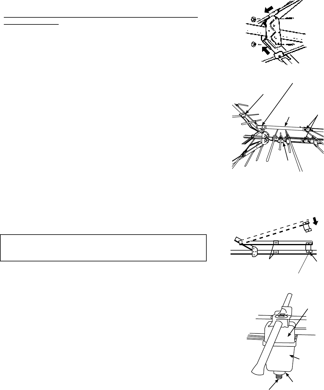
A. Unfold the elements on the corner reector booms as shown in Figure 4.
Element clip tips should point away from end of the boom with the hole.
Note: On HD8200U ONLY! It is not important whether or not the
V-shaped tuning stubs are touching the boom.
B. Attach the corner reector booms as shown in Figure 4A using the supplied bolts
and nuts.
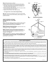
Step 6: Boom Brace
A. Install the boom brace by rst removing the bolts and hex nuts.
B. With the cartridge housing facing down, install the boom brace to the
top corner reector boom rst (see Figure 5) making sure the mast clamps are
on the same side as shown in Figure 5. Only nger tighten the bolt and hex nut.
C. Swing the other end of the boom brace down onto the rear section and insert the
bolt and hex nut (see Figure 6).
D. Tighten both bolts and nuts (on each end of the boom brace) securely.
Step 7: Cartridge Housing
A. Attach the housing cover so all 4 snaps are locked in place (as shown in Fig. 7).
Step 8: Coaxial Cable
A. Slide the rubber boot over the end of the coaxial cable. If your coax cable has
factory connectors on it, clip small end of boot off, so boot will slip over connector.
B. Attach the F-connector to the coaxial cable.
C. Attach the coaxial cable to the cartridge housing (see Figure 7).
D. Slide the boot over the boot collar on the housing.
Fig. 7
Attach Coax
Cable Here
Cartridge
Housing
Fig. 5
Cartridge
Housing
Mast
Clamps
Boom
Brace
Top corner
reector
Install this end rst
Boot Collar
Fig. 4A
Fig. 6
Mast
Clamps
Reector
Boom
Bolt
Main
Boom
Swing
Down
Install
this end
second
Cartridge
Housing
Cover