


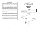
Fig. 2
Fig. 1
STEP 1. Unfold the elements on the top
and bottom reflector booms. Swing the
elements out until they lock into position.
See Figure 1. Unfold reflector booms until
they lock into place. See Figure 2.
STEP 2. Unfold all elements making sure
they lock into place.
MODEL HD-9032
STEP 3. Remove the bolt and hex nut
holding the element on the tapered end
of the front boom. Slide the two sections
together. The elements should be on top.
Replace the element, bolt and hex nut
and tighten securely. See Fig. 3.
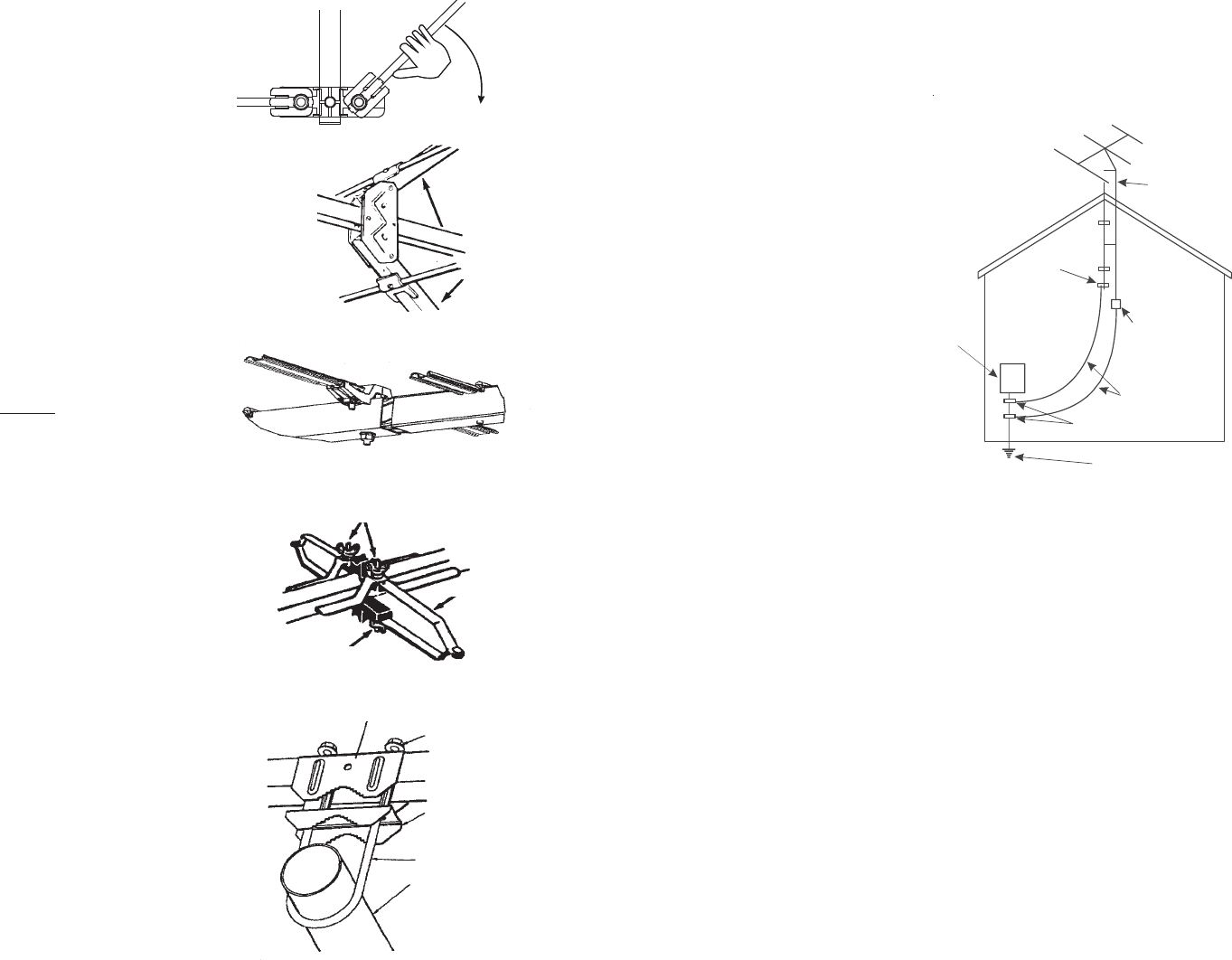
HOW TO PROVIDE
LIGHTNING PROTECTION
FOR TV ANTENNA AND SET
Step 1. Mount the lightning arrestor or 75 ohm
grounding block as close as possible to
where the 75 ohm coaxial cable downlead
enters the house. See Fig. 6.
Step 2. The ground wires for both the mast
and the downlead should be copper or alu-
minum wire, number eight (8) or larger. See
Figure 6.
Step 3. The downlead wire from the
antenna to the grounding block and the
mast ground wire should be secured to the
house spaced from four (4) to six (6) feet
apart. See Figure 6.
NOTE: In the case of a “ground up” antenna
installation, it may not be necessary to ground
the mast if the mast extends four or more feet
into the earth. Consult a TV serviceman for
the proper depth in your location.
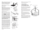
Fig. 4
STEP 4. Be sure to unfold tetrapole ele-
ments away from boom.
STEP 5. Connect matching transformer
to the downlead connection. Loosen wing
nuts on the bottom side of the tetrapole,
and slide spade lugs of matching trans-
former between the washers. Tighten wing
nuts securely. See Figure 4. If a VHF an-
tenna is coupled in with this antenna, the
VHF lead attaches to the top set of connec-
tions on the tetrapole. Note: If you are cou-
pling a VHF/UHF antenna to the top VHF
tetrapole connections, you will lose CH.14-
69 from the VHF/UHF antenna.
STEP 6. Remove the mast clamp insert,
U-bolt, and hex nuts from the supplied
hardware bag. Align insert with mast clamp
on main antenna boom. Attach U-bolt
through mast clamp insert and holes on
the side of main boom, extending threaded
bolt ends through holes to allow finger
tightening of hex nuts to boom. Mount
antenna to the mast by sliding U-Bolt
through top of mast, keeping mast be-
tween the rounded U-bolt edge and the
insert. Tighten hex nuts securely to lock
the antenna to the mast, keeping main
antenna boom level. See Figure 5.
STEP 7. Tape coax to mast with a good
quality electrical tape to prevent wind
whipping.
Fig. 6
Fig. 5
Fig. 3
MASTING
2” OD MAX.
MAST CLAMP
MAST CLAMP
INSERT
HEX NUT
U-BOLT
STEP 8. Ground antenna and mast per Safety
Instruction Sheet. See Figure 6.
ATTACH VHF COUPLING LEAD HERE
TETRAPOLE
ATTACH DOWNLEAD HERE
Antenna Lead
In Wire
Ground
Clamp
Electric
Service
Equipment
Antenna
Discharge Unit
(NEC Section 810-20)
Power Service Grounding
Electrode System
(NEC Art 250, Part H)
Ground
Clamps
Grounding Conductors
(NEC Section 810-21)
NEC - National Electrical Code
Example of antenna grounding as per
National Electrical Code, ANSI/NFPA 70
(May substitute a 75 ohm
Coax Grounding Block)