6
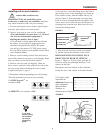
10. Clean roof area where the base feet will be
attached to the roof. Do not erase your marks!
11. Put approved sealant in the area under the base
feet. Place base foot on top of the sealant and
screw down using (2) #10 screws (provided) for
each base foot.
12. Unscrew the locknuts in the base and remove
the base from feet. Put the other (4) #10 screws
into the roof through the remaining holes in the
base feet.
Installation
ROOF INSTALLATION, continued
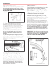
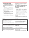
9.
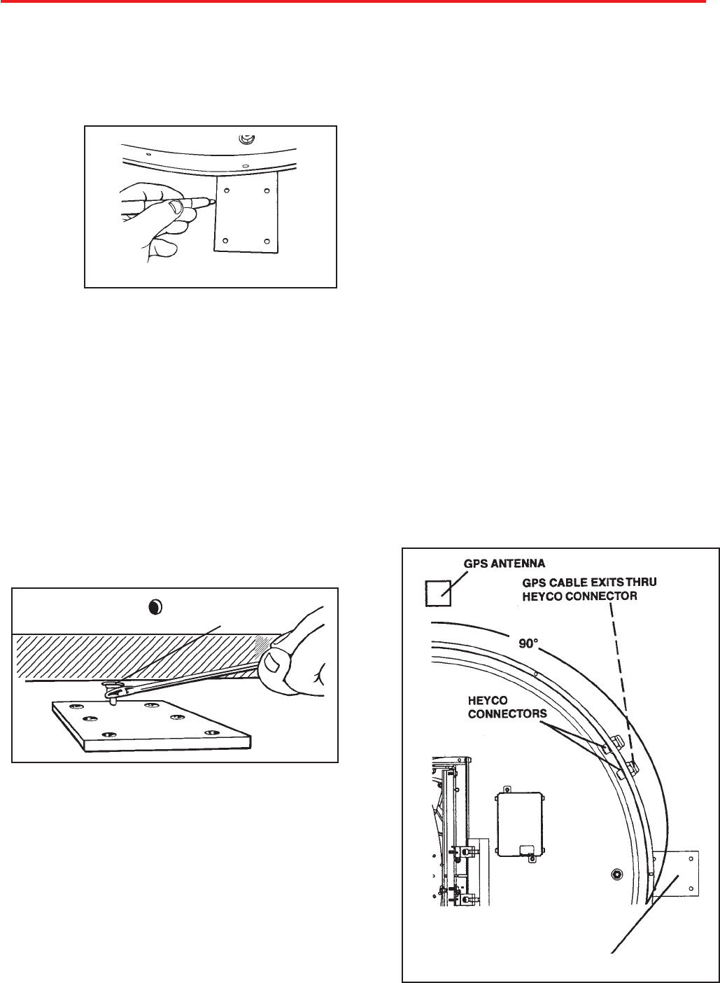
Place the unit on the roof in its permanent location
and mark around the base bracket, Figure 4. (Make
sure the rear adjustable base foot is directly facing
the back of the coach.)
FIGURE 4
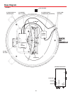
FIGURE 5
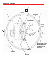
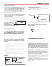
The GPS antenna is pre-wired and has a 3 foot cable
running through one of the Heyco
®
connectors.
When deciding where to place GPS antenna, DO
NOT SECURE! After wiring the receiver and initializ-
ing your system, you will need to test the system
(“Initializing and replacing dome” on page8).
Determine location for GPS antenna. It is recom-
mended you place the GPS antenna between unit base
and side edge of vehicle, 90° from rear mounting
bracket, Figure 6.
The recommended location for the GPS antenna is
based on having a level location and a clear view of
the sky. If another location, further from the base, is
desired, loosen the Heyco connector and pull out addi-
tional wire in the base. You must re-wrap and re-tie
the GPS cable inside the dome to prevent interfer-
ence with the LNBF. Failure to do so will result in
malfunction! Tighten Heyco connectors when done.
IMPORTANT! The GPS must be located away from
obstructions on roof of vehicle and other obstructions
such as trees, tall buildings, etc. You must have a
clear view of the sky for proper operation.
GPS installation —
FIGURE 6
13. After all base brackets are secured to roof, put
sealant on top of foot and screws. Place base on level-
ing screws located on base feet and install nut and
rubber washer on leveling screw.
14. Leveling the base is done by tightening or loosen-
ing the flange nut under the base, Figure 5.
Use an electronic level to adjust base so there is no
more than +/- 1° off level in all directions. Place
level on base of unit if possible. (If your level will not
fit inside the base plate, place on outside edge.) Level
front to back and side to side. Raise and lower by ad-
justing flange nut under base. After leveling base,
secure inside base with rubber washer, rubber side
down toward base, and lock nut.
BASE EXTERIOR
FOOT
LEVELING
SCREW/FLANGE
REAR MOUNTING FOOT


