


9
1. Decide the best location for the cables to en-
ter the vehicle, keeping in mind the desired
location for the switch and receiver.
Drill a 3/4” hole in the roof, push wires inside.
Make proper connections (remember you must
have
filtered +12 VDC power source).
2. Place cable-entry plate over hole and cables.
Screw in place. Seal plate and screw holes with
approved sealant (not included).
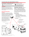
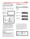
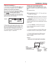
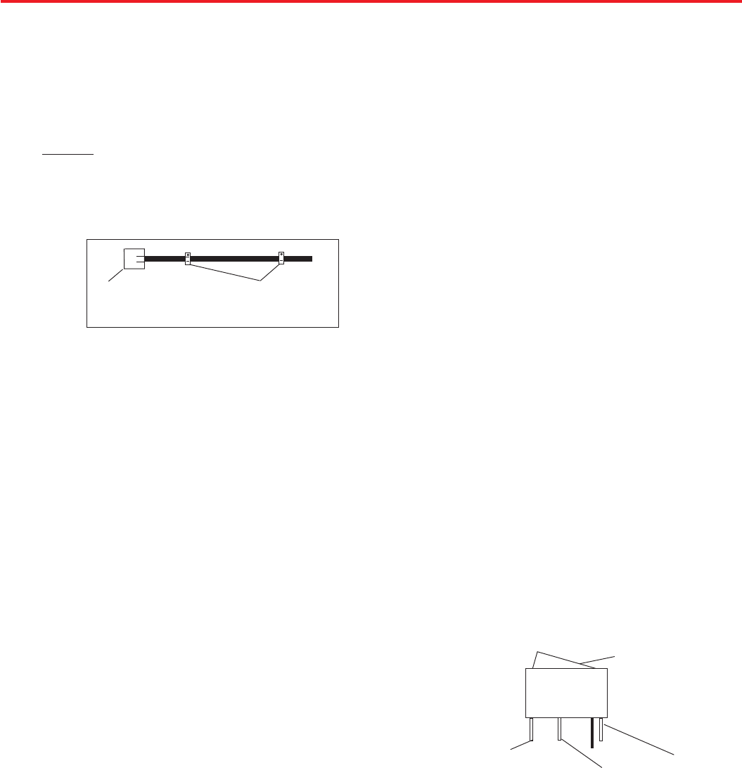
Cable entry installation —
3. Depending on the length of the cable on the
roof, you may need to use cable clamps or wire
ties (not provided) between the unit and your
cable-entry plate. Clamping the cable every 12”-
16” should eliminate any unnecessary cable
movement, Figure 7, see above.
Installation • Wiring
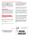
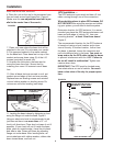
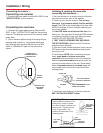
INSTALLING THE POWER SWITCH
1. Decide the location of the power on/off switch.
Be sure the switch is turned off before you be-
gin!
See diagram below.
Wall or panel mount: Drill 1-1/4” hole, pull wires
through wall or panel.
Surface mount: Determine location and direction
of box. Mount box feed wire into one of the box
openings.
Select plate cover (brown or white provided) and
snap the rocker switch into the switch plate. Be sure
switch is off!
2. Connect filtered +12 VDC power from ve-
hicle, using red spade connector, to isolated
spade on switch.
3. Connect red power wire from MV-3500 using
red spade connector to center spade on switch.
4. Connect vehicle ground and black ground
wire, using yellow spade connector, to silver
spade on switch.
INSTALLING THE POWER SWITCH DIAGRAM
FIGURE 8
CABLE-
ENTRY
PLATE
CABLE CLAMP -
EVERY12”-16”
FIGURE 7
FILTERED
+12 VDC
FROM
VEHICLE
STEP 4
STEP 3
STEP 2
TWO BLACK GROUND WIRES
1 FROM VEHICLE
1 FROM SATELLITE DISH
ON/OFF ROCKER
WITH LIGHT
(SHOWN IN OFF
POSITION.)
RED POWER
WIRE SATEL-
LITE DISH