


ASSEMBLY
MOUNT ASSEMBLY
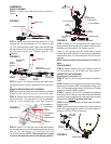
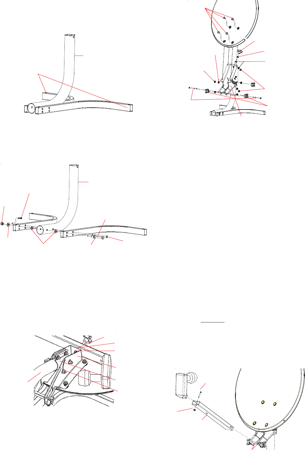
STEP 1. Position legs and mount pipe as shown in
Figure 1.
MOUNT PIPE/DISH BRACKET ASSEMBLY
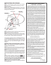
STEP 4. Line up long bolt inside dish bracket assembly
(Figure 4) with the slots on top of the mount pipe.
STEP 5. Secure dish bracket assembly to mount pipe
with (2) 1/4-20 x 1” carriage bolts, (2) 1/4” flat washers,
and (2) 1/4-20 flanged hex nuts. See Figure 3.
FIGURE 1
FIGURE 2
STEP 2. Attach mount pipe and legs using (2) 1/4” flat
washers, (2) 1/4” nylon washers, (1) 1/4” nylock nut, and
(1) 3-1/2” hex head cap screw. Insert the screw through
the top left hole of leg as shown in Figure 2. Insert wash-
ers and install nylock nut. Tighten using (2) 7/16”
wrenches.
STEP 3. Insert 3-1/2” clevis pin into the top-right hole of
the leg as shown in Figure 2. Secure with hair spring cot-
ter.
STEP 6. Insert 2-1/2” hex bolt from inside dish bracket
out through hole on top of dish bracket assembly. Secure
with (1) 1/4” flat washer, (1) 1/4-20 hex nut, and
1/4-20 locking knob. NOTE: The locking knob is used
to secure the feed tube when in the storage position.
FIGURE 4
STEP 7. Install (1) 1/2” carriage bolt into inside hole of
clamp bracket (side opposite of numbers on dish bracket
assembly) and secure with 1/4” washer and nut.
Install (1) 1/2” carriage bolt into inside hole of clamp
bracket (side with numbers on dish bracket assembly).
Insert washer over 1/2” bolt and secure with 1/4-20 lock-
ing knob.
NOTE: Stud should be facing outward. For both 1/2”
bolts.
DISH ASSEMBLY
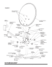
STEP 8. Attach reflector using (4) reflector bolts, (4)
1/4” flat washers, (4) 1/4-20 hex nuts. See Figure 4.
LNBF/FEED TUBE ASSEMBLY
(See Figure 5 for steps 9-13)
STEP 9. Feed 5’ coax through feed tube and attach to
LNBF.
STEP 10. Make sure the square hole is facing up on the
feed tube, then attach LNBF to the feed tube using (1) 8-
32 x 1-1/4” carriage bolt and using (1) 8-32 hex nut. Tighten
enough so that the LNBF is secure.
STEP 11. Insert (2) 1/4-20 x 2.5” carriage bolts (opposite
directions) into the bottom two holes of the dish bracket
assembly. Insert a washer and a locking knob onto each
threaded bolt. DO NOT tighten at this time.
STEP 12. Slide feed tube onto carriage bolts and tighten
locking knobs.
STEP 13. Attach splicing connector to 5’ cable and then
attach 20’ coaxial cable to splicer. 20’ coaxial cable at-
taches to “SATELLITE IN” on receiver.
MOUNT PIPE
LEGS (SHORT ENDS)
HAIR SPRING
COTTER
MOUNT PIPE
1/4” FLAT
WASHER
1/4” FLAT
WASHER
1/4” NYLON
WASHER
3-1/2” x 1/4”
CLEVIS PIN
1/4-20 x 3-1/2”
HEX HEAD CAP SCREW
1/4-20
NYLOCK
HEX NUT
DISH BRACKET ASSEMBLY
1/4-20 HEX NUT
2-1/2”
HEX BOLT
CLAMP BRACKET
1/2”
HEX BOLT
MOUNT PIPE
DISH BRACKET
ASSEMBLY
FIGURE 3
1/4” FLAT WASHER
REFLECTOR
BOLT
1/4” FLAT WASHER
1/4-20
HEX NUT
2.5” CARRIAGE
BOLTS
LOCKING KNOB
1/4-20
HEX NUT
1/4-20
LOCKING KNOB
1/4-20 HEX NUT
1/4” FLAT WASHER
FIGURE 5
8-32
HEX NUT
FEED TUBE
8-32 x 1.25”
CARRIAGE
BOLT
CARRIAGE BOLTS